VS
07.94
1-115
Siemens AG 1997 All Rights reserved
SIMODRIVE 611A Installation and Start–Up Guide/IAA/–04.97 Edition
Table 5-6 Normalization via potentiometer R903 (when supplied, factor = 1)
Pot. R903
0 1 2 3 4 5 6 7 8 9 10
Normalization
Factor
3 2.8 2.6 2.4 2.2 2.0 1.8 1.6 1.4 1.2 1
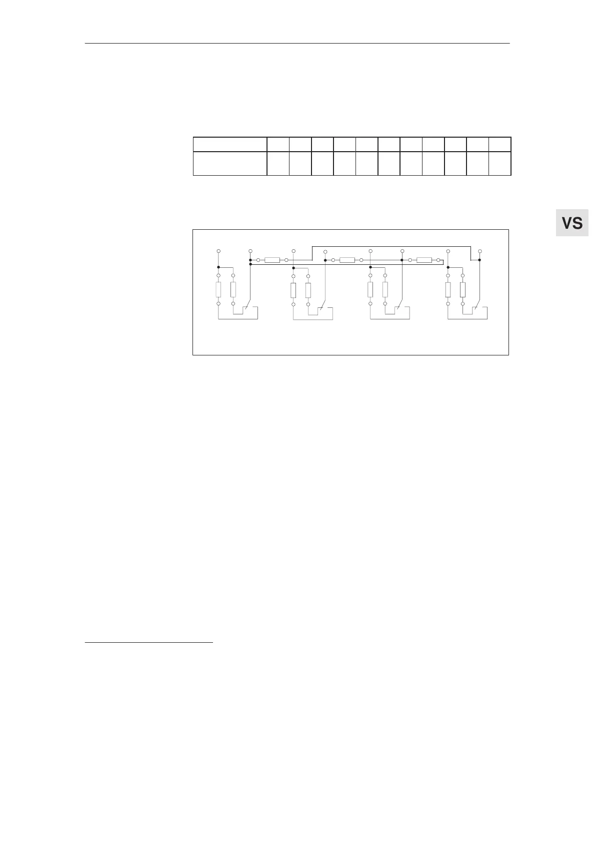
Terminal selected using 0 Ω resistors
T.110
R170 R106
1)
R98
R103 R97
1)
T.108 T.115 T.114 T.216 T.214 T.127 T.126
R105
1)
R99
1)
R108
1)
R171
1)
R107
R104
1)
n
act
= n
set
3)
|I
act
|> I
x
2)
|n
act
|< n
min
3)
|n
act
|< n
x
3)
Fig. 5-2 Relay functions
1)As supplied
2)Relay drops out
3)Relay pulls–in if the function is fulfilled.
Normalization of-
jM/Pj display
Relay function, li-
mit value stage
output
Feed modules (VS)
04.97 5.1.1 Settings with the control board removed