VS
07.94
1-116
Siemens AG 1997 All Rights reserved
SIMODRIVE 611A Installation and Start–Up Guide/IAA/–04.97 Edition
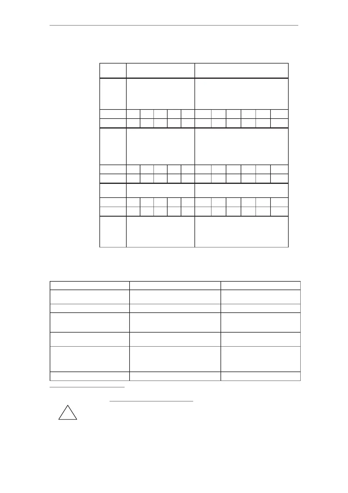
Table 5-7 Limit value functions
Limit va-
lue stage
Range Settings via fixed values
jI
act
juI
x
pot. R211
4.5 %...100 %
Smoothing for relay contact bounce = C87
Suppressed: n
set
step u31 mV,
R180 = 0 Ω
hysteresis = 10 mV,
R179 = 2 kΩ
Pot. R211 0 1 2 3 4 5 6 7 8 9 10
I
x
=in % 100 90 81 71 62 52 43 33 24 14 4.5
jn
act
jtn
mi
n
pot. R10
0.3 %...1.7 % n
max
Smoothing for relay contact bounce = C68,
400 mV hysteresis (as supplied),
inactive for C axis: R100 = 0 Ω (as sup-
plied)
R274 = 300 kΩ, corresponds to 20 mV hy-
steresis
Pot. R10 0 1 2 3 4 5 6 7 8 9 10
n
min
=in % 0.3 0.44 0.58 0.73 0.87 1.02 1.16 1.31 1.45 1.59 1.74
jn
act
jtn
x
pot. R43
3 %...100 % n
max
Relay contact bounce smoothing = C68
Pot. R43 0 1 2 3 4 5 6 7 8 9 10
n
x
=in % 3.4 13 23 34 44 54 64 74 84 94 104
n
set
=
n
set
*
Only in main spindle operation
Monitoring threshold:
n
set
– difft20 mV,
R179 = 2 kΩ
hysteresis = 10 mV, R180 = 0 Ω
extension = 32 ms, C20 = 1 µF
Table 5-8 Settings via fixed values
Function
Component(s) Effect
Ramp–function generator tracking R270 = 0 Ω (as supplied)
R270 = open
Tracking active
Tracking inactive
Speed setpoint smoothing C40 τ [ms] = 10 C40 [µF]
Correction setpoint for main spindle
operation (term.65 brakes to setpo-
int, term.24)
2)
R900 + R901 = open (as supplied)
R900 + 901 = 40 kΩ
No correction setpoint
Correction setpoint via T.24/20
Current actual value/power display R160 = open, R207 = 1 kΩ (as supplied)
R160 = 1 kΩ, R207 = open
jM/Pj–display
jI
act
j–display
C–axis/main spindle drive op.
setpoint, MSD: term.56/14
setpoint, C axis: term.24/20 or
fixed setpoint via term.22 or term.23
Terminal 61 = open
Terminal 61 at term.9
Main spindle drive operation
C–axis operation
Changeover, refer to Fig. 5–3
Changeover speed, term.61 R77/78
1)
1)
Changeover speed =
R77
.
(47000 – R78
.
15)
R77
.
47 k + R78
.
(R77 + 47 k)
[%]
2)
!
Warning: The pulses are only canceled when the n
off
threshold is fallen below!
Functions via fixed
values
Feed modules (VS)
04.975.1.1 Settings with the control board removed