VS
07.94
1-117
Siemens AG 1997 All Rights reserved
SIMODRIVE 611A Installation and Start–Up Guide/IAA/–04.97 Edition
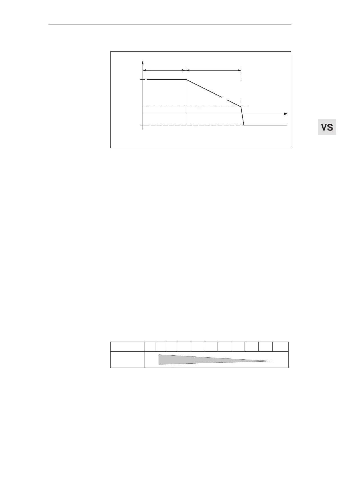
R77 and R78
t
Braking range
Term.61 = H (w. r. t. term.9)
MSD
operation
Term.61=open
Parameter
changeover
point
Speed
n1
n2
Change–
over
speed
n1 = main spindle drive speed
n2 = C–axis speed
Fig. 5-3 Changeover function, terminal 61
Closed–loop control parameters, drift setting, setpoint input
Adaptation enable
200 ms timer switched–in
Several relay functions inhibited
n
off
shutdown inhibited
Settings in operation
1.Set the C–axis parameters via the parameter board (tachometer, T
N
, K
P
,
drift).
C–axis parameters, refer to the speed controller optimization, Section 2
2.Set the main spindle drive parameters via potentiometers on the option
board front panel:
Pot. R44 02345678 10
Pot. R35=ccw
Pot. R35=cw
2
15
1
1
1
9
Fig. 5-4 Extending the integral action time using pot. R44 and the influence of pot. R35
on the parameter board, extending T
N
by a specific factor
Parameter chan-
geover for C–axis
operation
Setting rule
Feed modules (VS)
04.97 5.1.1 Settings with the control board removed