9
02.98
1-154
Siemens AG 1998 All Rights reserved 6SN1197–0AA00 02.98 Edition
SIMODRIVE 611 (PJ)
Power
controller
Logic
control
6
K1+
K1
AS1AS2T. 9
T. 663
FR–
M
Drive 1
AS1T. 9 T. 112 T. 19 T. 48
FR+ FR–
FR–
KS
Logic
Control
Power
con-
troller
P500
M500
M
Logic
con-
trol
6
Pre–
charging
contactor
+
KS
FR+
NS1
NS2
T. 63
T. 64
MS
MS
K1
K2
K2
Line
contactor
Voltage
supply
K1
MS
I/R – UE module
U1 V1W1
D1
F1 F2 F3
L1 L2 L3
Main
switch
T. 213
T. 111
Power
controller
Logic
control
6
K1+
K1
AS1AS2T. 9
T. 663
FR–
M
Drive n
Drive inhibited
Working zone 1
T. 9
Drive inhibited
Working zone 2
T. 663
drive 1
T. 663
drive 2
T. 663
drive 3
AS2
1)
Terminals for the user
T. ...
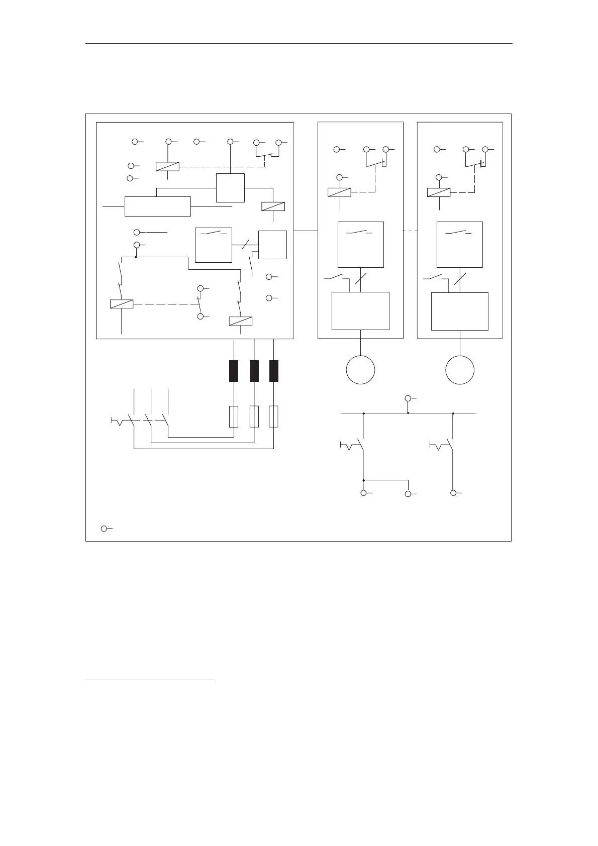
Figure 9-8Block diagram 1; valid for UE modules 5/10kW to 28/50kW and I/R modules 16/21kW to 55/71kW
K1, pre–charging contactor contact, positively driven
K2, line contactor contact, positively driven
Terminals 111, 213 NC contacts, positively driven to the NO power contacts
Terminal P500, M500, terminals for the power supply for the connection to
the power DC link
Only floating contacts may be connected between terminals NS1 and NS2
1)Relay KS and terminals AS1, AS2 are not provided for the UE module. As there is no step–up controller in the UE
module, the voltage cannot be increased above the rectified line voltage level.
Block diagram 1
9.5.9 Application examples