9
02.98
1-155
Siemens AG 1998 All Rights reserved 6SN1197–0AA00 02.98 Edition
SIMODRIVE 611 (PJ)
Power
controller
Logic
control
6
K1+
K1
AS1AS2T. 9
T. 663
FR–
M
Drive 1
AS1T. 9 T. 112 T. 19 T. 48
FR+ FR–
FR–
KS
Logic
Control
Power
con-
troller
P500
M500
M
Logic
con-
trol
6
Pre–
charging
contactor
+
KS
FR+
NS1
NS2
T. 63
T. 64
MS
MS
K1
K2
K2
Line
contac-
tor
Voltage
supply
K1
MS
I/R module
U1 V1W1
D1
F1 F2 F3
L1 L2 L3
Main
switch
T. 213
T. 111
Power
controller
Logic
control
6
K1+
K1
AS1AS2T. 9
T. 663
FR–
M
Drive n
Drive inhibited
Working zone 1
T. 9
Drive inhibited
Working zone 2
T. 663
drive 1
T. 663
drive 2
T. 663
drive 3
AS2
Terminals for the user
T. ...
K2
K3
L1 L2
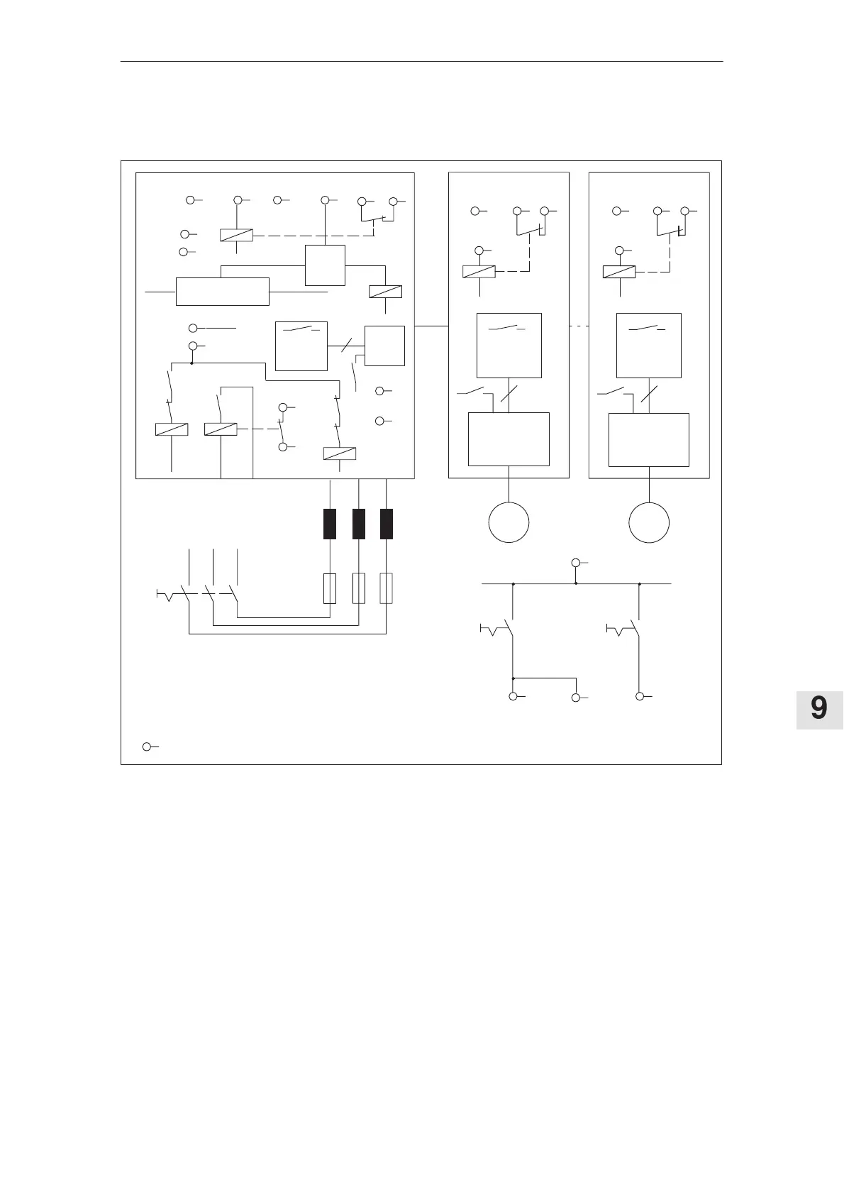
Figure 9-9Block diagram 2; valid for I/R module 80/104 kW and I/R module 120/156 kW
K1, pre–charging contactor contact, positively driven
K2, holding contactor contact
K3, line contactor contact, positively driven
Terminals 111, 213 NC contact positively driven to the NO power contacts
Terminal P500, M500, terminals for the power supply for the connection to
the power DC link
Only floating switching contacts may be connected between terminals NS1
and NS2.
Block diagram 2
9.5.9 Application examples