611V3usa.PPT
Section A Power and Grounding
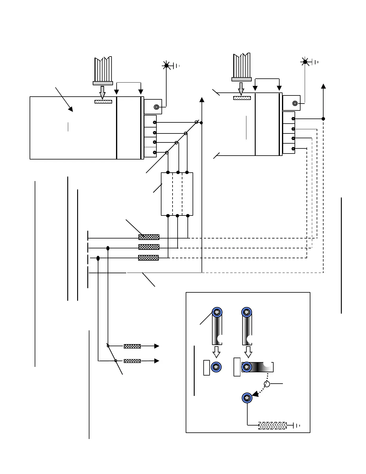
P600
M600
Internal
100K Ohm
Resistor
NOTE: Connect link to Resistor.
This connection provides a reference to
Earth Ground for M600. Do Not connect
M600 directly to earth ground!
Links from
adjacent Module(s).
Detail A . . . A
1)
1U1 1U2
1V1 1V2
1W1 1W2
To “PE1” of all
other Drive Modules
To CNC “Star”Ground
Point
Ribbon Cable from
adjacent Module
I/R 16, 36, or 55KW
6SN1145-1B . 0 . -0 . . 1
OR
U/E 28KW
6SN1145-1AA00-0CA0
U1 V1 W1 PE1 X131
A
A
DC Link
Cover
Ribbon Cable from
adjacent Module
U1 V1 W1 PE1 X131
A
A
DC Link
Cover
Wiring Scheme for the
Unregulated Version U/E
Module(commutating
reactor not required).
To “PE1” of all
other Drive Modules
To CNC “Star”Ground
Point
2)
3)
Sheet 1 / 3 - 8 / 10 / 98
Required I/R - U/E Connections With Commutating Reactor
4)
For explanation of notes [ *)], see sheet 3/3
6SN1146- 1AB00- 0BA1
6SN1145- 1AA01- 0AA1
U/E Module
5, 10 kW
400/415VAC, 50/60HZ, +/- 10% or
480VAC, 50/60HZ, +6%, -10%
Grnd. L1 L2 L3
8)
To L1-L2 terminals on 80
and 120KW I/R modules only
9)
F1 F2
External Pulsed Resistor
required for U/E 28KW
6SN1113-1AA00-0 . A0
 Loading...


