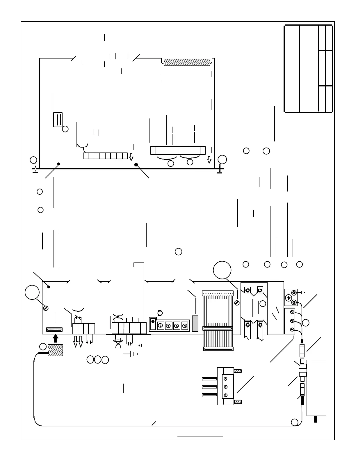
S2-DIP(Underlined = Factory Setting)
10 Torque [current] Mode(on) /
9 Velocity mode(off)
8 Current Loop
7 Gain(off)
6
5
4 Current
3 Limit(off)
2
1 Motor Rotation Direction vs. Volt-
age polarity @ X331 - 56 & 14(on)
6
Current Controller Integrator active(on) or
not active(off)(Torque(Current) Mode only).
Master(off) / Slave(on)
Ready(off) / Fault(on) Selection
Speed Controller Adaption not active(off) / active(on)
Current Command Smoothing not active(off) / active(on)
Velocity Controller Smoothing not active(off) / active(on)
Tachometer Smoothing not active(off) / active(on)
Velocity Command Smoothing not active(off) / active(on)
W2 V2 U2
Alternate Connector Styles ,
(Depending on Module
Current Rating )
6FC9348 - 7AT
Cable 6FX2002 - 2CB31 - 1 . . 0
6FC9348 - 7D . . . or
6FX2003 - 0C . . .
Cable 6FX2002 - 5BA . . - 1 . . 0
Siemens Energy & Automation
Machine Industry Business
6 / 10 / 96 A-3 de
Interface Drawing for ;
Date
Revision
Drawn by
PAGE 1 / 3
1FT5... AC
Servo Motor
6FX2003-0CE12
(12 Pins)
(6 Pins)
1 External, installer provided connections ,
are shown on the left side of the
connectors and internal on the right.
2 Solid line connections are the minimum
required for axis operation.
3 Broken line connections and Arrows are
optional.
NOTES
611-A SERVO, STANDARD VERSION
1
2
3
X311
DC Link
Cover
6SN1118- 0AD11- 0AA0
(PCB) (Pwr. Sect.)
6SN1123- 1AA0 . -0 . A0
U2 V2 W2
Ribbon
Cable
BUS
5
K
P
T
N
Adapt
Drift(Balance)
T
Primary Velocity (or Torque)
Command Input
Controller Enable
FR+ (P24 for Enables)
Select “Torque Mode”
+ / - 10 VDC (Twisted & Shielded
Pair) Ground only at CNC end.
(If no CNC, connect directly
to ground)
56
14
65
9
22
9
X331
- - - -
- - - -
AS1
AS2
663
9
X321
Status of the “Drive Signals”
to the Output Transistors
Pulse Enable
FR+ (P24 for Enables)
4
4
4
S1 Tacho Jumpers
(See page 3, Sect. 3-A)
8
7
6
5
4
3
2
1
S3-DIP(Underlined = Factory Setting)
X
3
0
1
5 For connection details, see Drawing:;
“ General Wiring for Power, Grounding and
Module interconnection”.
Remove PCB / Panel Assy.
from Module to access switches.
( Loosen Captive screws a. and b.
then carefully pull Assy. out of Module .
When replacing, be sure to firmly tighten
Captive screws. )
a.
a.
b.
b.
WARNING: Board components
can be damaged if not handled
carefully. Do not touch
components or connecting
foil.
6
6
( on )
( on )
4 For additional details on Motor to Drive connections,
Test Points and the LED display, see page 2 / 2
6 The correct setting of these Items(3 places)
must be verified prior to motor operation.
Test Points and
LED’s ( see pg. 2 / 3 )
( Component Side )
4
SECTION F
(6SY9433 x2)
(6SY9896)
6SY9904
 Loading...


