Siemens Energy & Automation
Machine Industry Business
6 / 10 / 96 A-3 de
Interface Drawing for ;
Date
Revision
Drawn by
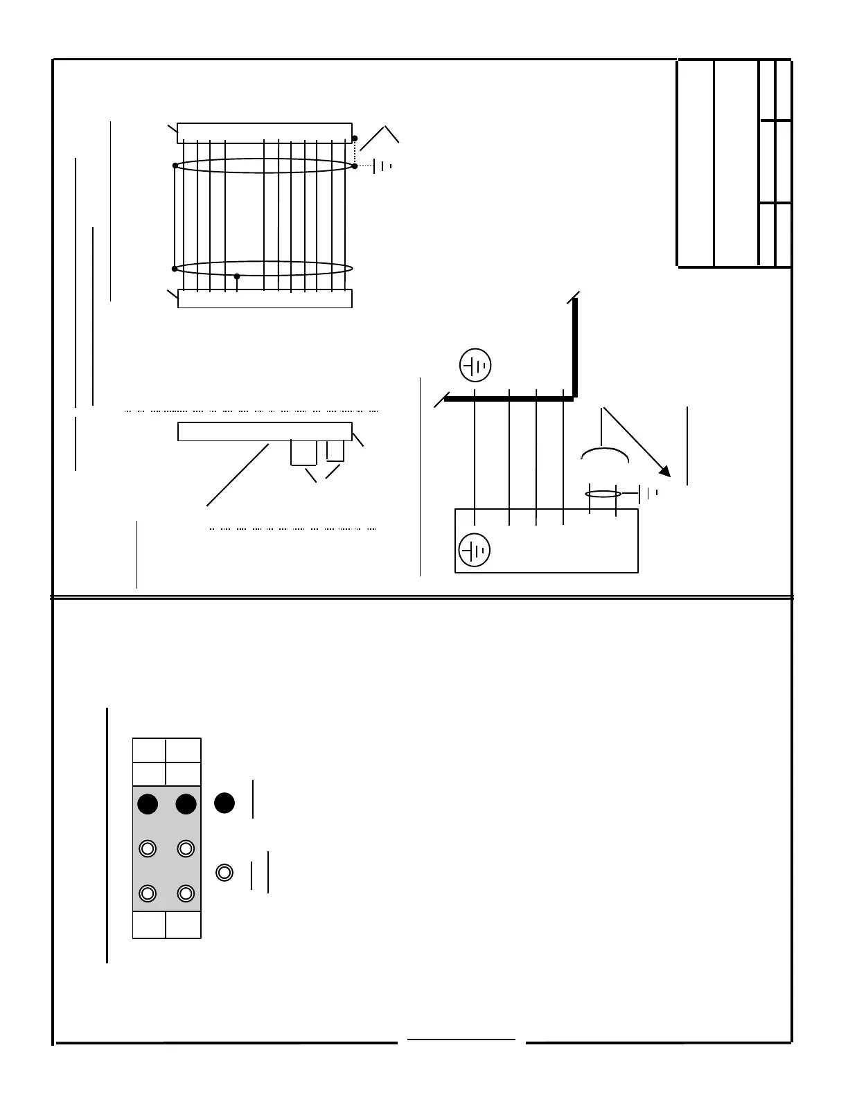
611-A SERVO, STANDARD VERSION
Wiring of Motor to Drive F/B Cable
Tacho, Rotor Position & Thermistor
( suggested Wire Size AWG 22 or 24 )
11
12
7
6
8
4
3
1
2
5
9
10
8
15
7
14
1
9
4
6
13
5
2
11
12
6FC9348-7AT
( Drive End )
NOTE: Motor to Drive connections
must be exactly as shown !
Connections for Optional Brake:
[24 VDC + / - 10%; Current range 0.4 to 3.25 Amps.,
dependent on Motor / Brake size].
If not used, all three (3) wires should be connected
to ground.
611-A AC SERVO
Feed Module
1 ( U )
2 ( V )
6 ( W )
5 ( BR2 )
4 ( BR )
U2
V2
W2
Wiring of Motor to Drive Power Cable
( Wire size dependent on Motor Type )
Tacho R
Tacho S
Tacho T
Tacho M
P15(RPG)
RPD R
RPD S
RPD T
M(Grnd.)
PTC
PTC
Page 2 / 3
Test Points and Fault LED’s
W
M
T M
X A
Test
Points
LED’s
W - Test Point = Actual Motor Current
( 10V = I-max as set in S2-DIP; 2, 3, 4 & 5 )
M - Test Point = Common reference for
all Test Points
T - Test Point = Current Command
X - Test Point = Actual Motor Speed
( 40.0 V Tacho: 10 V = Rated Speed )
( 16.5 V Tacho: 11 V = Rated Speed )
M - LED = Motor Fault;
- Motor to Drive Cable
- Tachometer
- Rotor Position Detector
A - LED = Axis(Drive) Fault
- Speed Controller at Limit ( > 200ms )
- Drive Heat Sink Overtemperature ( > 90
o
C)
- Motor Overtemperature ( > 155
o
C + / - 5
o
C)
- I
2
T Monitoring Activated ( I-rms > 1.1 x I-rated )
6FX2003-0CE12
( Motor End )
( - )
( + )
For correct Grounding, the Shield should
be connected( on the Drive end) to either the
Connector Shell, or the 5mm screw hole
on the top of the module.
Jumpers
6FX2003 - 1CF12
- - - - - - - - - - - - - -
Dummy Plug
If the Motor F/B Cable is
disconnected the Module
will fault. If this plug is
installed (at the motor end)
the fault will not occur.
- - - - - - - - - - - - - -
11
12
7
6
8
4
3
1
2
5
9
10
SECTION F
 Loading...


