W2 V2 U2W2 V2 U2
W2 V2 U2
6FC9348 - 7AT
6FC9348- 7D . . . or
6FX2003- 0C . . .
Cable
6FX2002 - 5BA . . - 1 . . 0
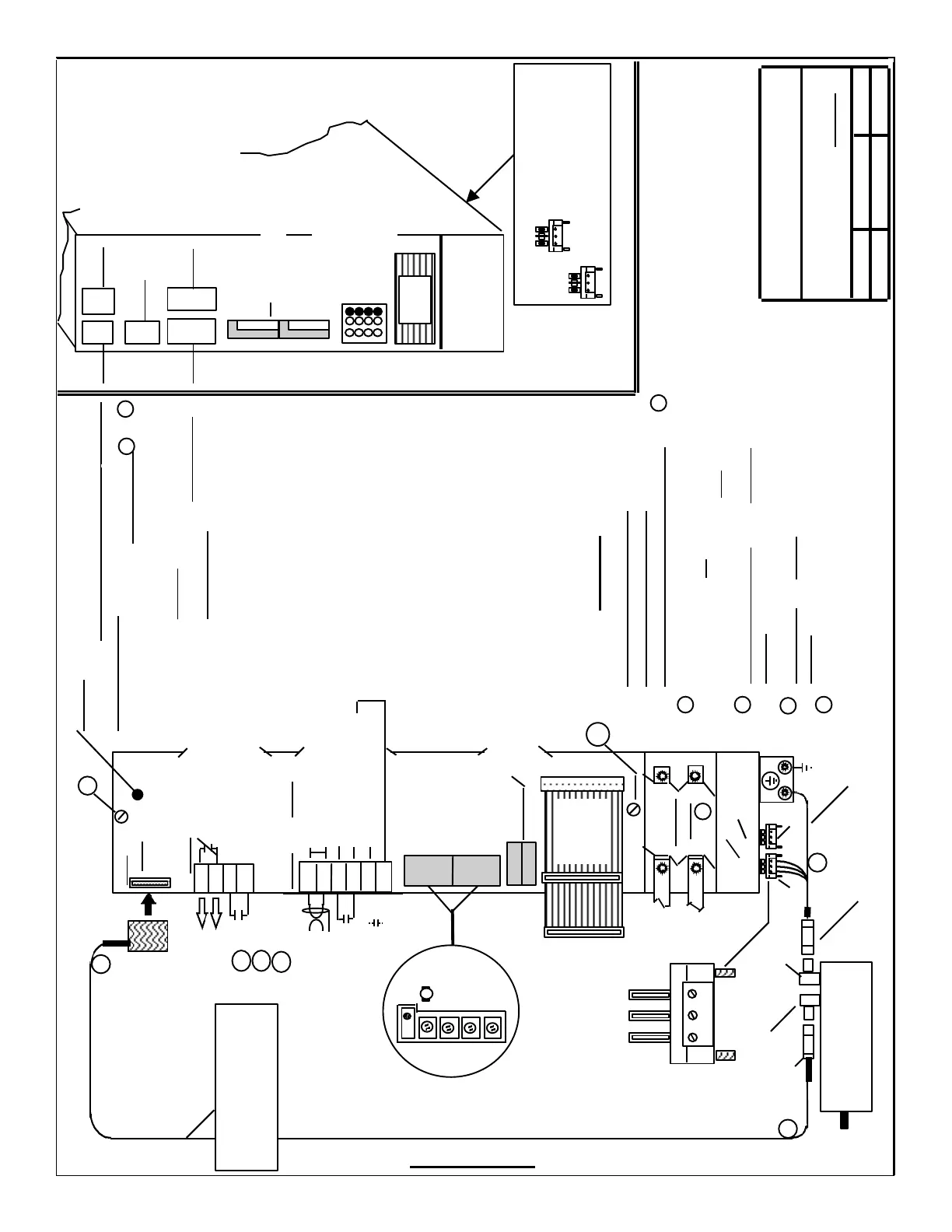
Siemens Energy & Automation
Machine Industry Business
6 / 10 / 96 A-5 de
Interface Drawing for ;
Date
Revision
Drawn by
PAGE 1 / 3
1FT5... AC
Servo Motor
6FX2003-0CE12
(12 Pins)
(6 Pins)
1 External, installer provided connections ,
are shown on the left side of the
connectors and internal on the right.
2 Solid line connections are the minimum
required for axis operation.
3 Broken lines and Arrows indicate
optional connections.
NOTES
611-A SERVO, 2 Axes ,
STANDARD VERSION
1
2
3
X311(A1)
X313(A2)
DC Link
Cover
6SN1118- 0AE11- 0AA0
(PCB) (Pwr. Sect.)
6SN1123-1AB00-0 . . 0
Ribbon
Cable
BUS
5
kp
TN
Adapt
Drift
T
+ / - 10 VDC (Twisted
& Shielded Pair)
56
14
65
9
22
9
X331(A1)-X332(A2)
- - - -
- - - -
AS1
AS2
663
9
X321
Status of the “Drive Signals”
to the Output Transistors
Pulse Enable
FR+ (P24 for Enables)
4
4
4
5 For connection details, see Drawing:;
“ General Wiring for Power, Grounding and
Module interconnection”.
a.
b.
4 For additional details on Motor to Drive connections,
Test Points and the LED display, see page 2 / 3
Test Points and
LED’s ( see pg. 2 / 2 )
(A1 & A2)
A1
A2
(A1) Indicates Axis “1”
(A2) Indicates Axis “2”
(B) Indicates Common to both
Axis 1
Axis 2
Axis 2
Axis 1
Axis 1(A1) motor shown
(A1)
(A2)
(B)
(A1) (A2)
(A2)
(A1)
(A2)
(A1)
X311 X313
X321
X332X331
Adjustments
Test
Points
&
Fault
LEDs
W2 V2
U2
W2 V2
U2
A1 - Rearmost
A2 - Forwardmost
( Located on Bottom of Module)
Assignment and
location of Front
Panel Components:
“A1” = Axis 1
“A2” = Axis 2
“B” = Common
to both
axes
Cable
6FX2002-2CB31 - 1 . . 0
NOTE: Prior to applying power or attempting to
operate motor, settings must be made on internally
located switches. To access, remove Front Panel &
PCB Assembly by losening the captive screws a. & b.
and sliding assembly out of it’s case. When re-installing,
be sure to tighten captive screws
securely . For location and function
of switches, please see page 2 / 2
of this drawing .
DC Link
Cover
Ribbon
Cable
Primary Velocity (or Torque)
Command Input
Controller Enable
FR+ (P24 for Enables)
Select “Torque Mode”
SECTION G
(6SY9433 x2)
(6SY9433 x2)
6SY9904
Part# 6SY9904
 Loading...


