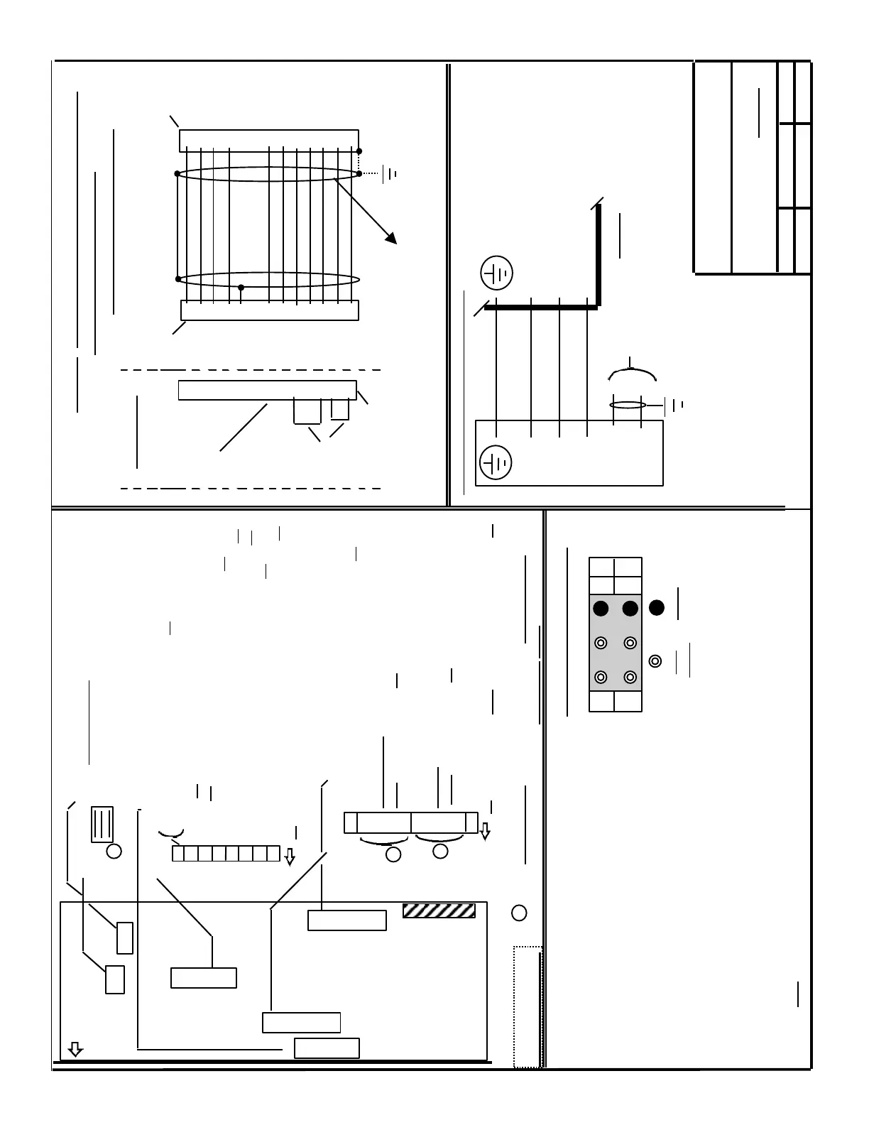
W - Test Point = Actual Motor Current
( 10V = I-max as set in S2(A1)-DIP; 2, 3, 4 & 5)
S5(A2)-DIP; 2, 3, 4 & 5)
M - Test Point = Common reference for all Test Points
T - Test Point = Current Command
X - Test Point = Actual Motor Speed
( 40.0 V Tacho: 10 V = Rated Speed )
( 16.5 V Tacho: 11 V = Rated Speed )
M - LED = Motor Fault; A - LED = Axis(Drive) Fault
- Motor to Drive Feed Back Cable - Speed Controller at Limit ( > 200ms )
- Tachometer - Drive Heat Sink Overtemperature ( > 90
o
C)
- Rotor Position Detector - Motor Overemperature ( > 155
o
C + / - 5
o
C)
- I
2
T Monitoring Activated ( I-rms > 1.1 x I-rated )
- Motor to Drive Power Cable disconnected
NOTE: If Both lights are lit, the Feed Back Cable may be disconnected(motor end ?)
Siemens Energy & Automation
Machine Industry Business
6 / 10 / 96 A-5 de
Interface Drawing for ;
Date
Revision
Drawn by
611-A SERVO, 2 Axes,
STANDARD VERSION
6FX2003-0CE12
( Motor End )
6FC9348-7AT
( Drive End )
Wiring of Motor to Drive F/B Cable
Tacho, Rotor Position & Thermistor
( suggested Wire Size AWG 22 or 24 )
NOTE: Motor to Drive connections
must be exactly as shown !
Connections for Optional (G45) Motor Mounted
Brake [24 VDC, + / - 10%; Current range 0.4 to 3.25
Amps., dependent on Motor / Brake size]. If not
used, all three (3) wires should be connected to
ground.
Tacho R
Tacho S
Tacho T
Tacho M
P15(RPG)
RPD R
RPD S
RPD T
M(Grnd.)
PTC
PTC
Page 2 / 3
11
12
7
6
8
4
3
1
2
5
9
10
Jumpers
Dummy Plug
If the Motor is
disconnected,
the Module
will not fault
if this plug
is installed
6FX2003-1CF12
- - - - - - - - - - - - - -
- - - - - - - - - - - - - -
Test Points and Fault LED’s
( A1 & A2 )
W
M
T M
X A
Test
Points
LED’s
S1(A1) & S4(A2) Tacho Jumpers
( close only for motors
with 16.5 V Tacho’s )
6
6
S2(A1) & S5(A2)-DIP(NOTE:Underlined = Factory setting)
10 Torque ( Current ) Mode( on ), Velocity Mode( off )
9
8 Current Loop
7 Gain ( Factory setting off)
6
5
4 Current
3 Limit ( Factory setting off)
2
1 Motor Rotation Direction vs. voltage polarity
@ terminals X33* - 56 & 14. ( Factory setting on )
6
( on )
8
7
6
5
4
3
2
1
S3(A1) & S6(A2)-DIP(NOTE: Underlined = Factory setting )
Current Controller integrator active (on) or
not active( off )-(Torque / Current Mode only) .
Master( off ) / Slave( on )
Ready( off ) / Fault( on ) Selection
Speed Controller Adaption active(on )/ not active( off )
Current Command Smoothing active( on ) / not active ( off )
Velocity Controller Smoothing active(on ) / not active ( off )
Tachometer Smoothing active( on ) / not active ( off )
Velocity Command Smoothing active( on ) / not active ( off )
( on )
X
3
0
1
S1
A1
S4
A2
S3
A1
S2
A1
S5
A2
S6
A2
6 The correct setting of these Items ( 3 places) must be verified
prior to motor operation. See Installation Guide for correct settings.
( Front Panel )
(Component side view )
CAUTION: Use
care while handling
to avoid damaging
components.
A1 = Axis 1
A2 = Axis 2
11
12
7
6
8
4
3
1
2
5
9
10
8
15
7
14
1
9
4
6
13
5
2
11
12
Note: For correct grounding of the Shield, this end
should be connected to the Connector Shell or to
the M5 screw hole in the top of the Module.
Wiring of Motor to Drive Power Cable ( Wire size dependent on Motor Type )
611-A AC SERVO
Feed Module
1 ( U )
2 ( V )
6 ( W )
5 ( BR2 )
4 ( BR )
U2
V2
W2
-
+
SECTION G
 Loading...


