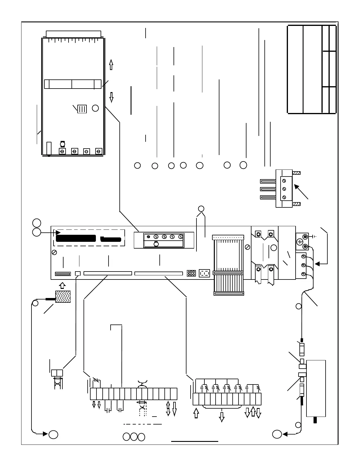
1 External, installer provided connections , are shown
on the left side of the connectors and internal on the right.
2 Solid line connections are the minimum required for
axis operation.
3 Broken line connections and Arrows are optional.
4 For additional details on Motor to Drive connections,
Test Points and the Status / Fault LED display, see Page 2 / 2.
5 If Drive is equiped with the “ Main Spindle Option “
( PCB P/N 6SN1114 - 0AA02 - 0AA0 ) the connections
and adjustments will be found on the seperate drawing ;
“ 611-A Servo Main Spindle Option “.
6 For connection details, see Drawing ; “ General Wiring
for Power, Grounding and Module Interconnection “.
W2 V2 U2
X311
X321
X331
X341
DC Link
Cover
Kp
TN
AD
Drift
T
6SN1118-0AA11-0AA1
(PCB) (Pwr. Sect.)
6SN1123-1AA . .- 0 . . 0
Primary Velocity
Command Input
56
14
+ / - 10 VDC
(Twisted &
Shielded Pair)
X321
AS1
AS2
663
9
65
9
22
23
20
24
96
44
6
258
16
- - - - -
- - - -| |- - - -
- - - -| |- - - -
- -| |- - -
- - - - - -
- - - -| |- - - -
X331
Status of the “Drive Signals”
to the Output Transistors
Pulse Enable
FR+ ( P24 for Enables )
Controller Enable
Internal Speed Command 1
Internal Speed Command 2
Secondary Velocity
Command Input
External Control of Current Limit
- 15 VDC / 10ma
Integrator Inhibit ( Velocity Loop )
Master / Slave ( Torque Command )
Iact - Actual Motor Current Output
X341
289
288
290
291
293
294
296
297
299
672
673
674
Common Input for Contacts
Speed Controller at Limit
I
2
T Activated
Motor Overtemperature
Tachometer / Rotor Position
Detector
Ready / Fault (As received = “Ready”-
Remove R33 on Parameter PCB= “Fault”)
U2 V2 W2
1FT5... AC
Servo Motor
A
A
Alternate Connector Styles ,
(Depending on Module
Current Rating )
T
Tn
Kp
S1
Tacho
Jumpers
(use only if
required)
Parameter Board - 6SN1114-0AA01-0AA0
Low Speed
Adaption
(Adaption not active
unless R34 installed )
Tachometer ( R11 )
Proportional
Gain
Integral
Gain
Drift / Balance ( R20)
( R25 )
( R35 )
AD ( R36 )
x
3
0
4
1
2
3
4
5
6
7
8
9
10
Direction
Current
Limt
Current
Loop Gain
Torque Mode
OFF / ON
S2
6FC9348-7AT
Cable
6FX2002-2CB31-1 . . 0
Cable 6FX2002-5 . A . .-1 . . 0
Siemens Energy & Automation
Machine Industry Business
6 / 3 / 97 A - 3 de
Interface Drawing for :
Date
Revision
Drawn by
PAGE 1 / 3
(12 Pins) (6 Pins)
Ribbon
Cable
BUS
Status / Fault
LED Display
Test
Points
4
4
4
4
5
NOTES
6
611-A SERVO, COMFORT VERSION
1
2
3
7 Special Note: If the Servo Module contains a “Main
Spindle Option”(PCB P/N 6SN1114- 0AA02- 0AA0 ),
components R4, R5 & C4(if installed) MUST BE REMOVED
from the Parameter Board 6SN1114 - 0AA01- 0AA0 prior
to applying power !
7
7
SECTION H
6FX2003-0CE12
6FC9348-7D. . . or
6FX2003-0C. . .
(6SY9433)
(6SY9902)
(6SY9901)
6SY9904
 Loading...


