11
12
7
6
8
4
3
1
2
5
9
10
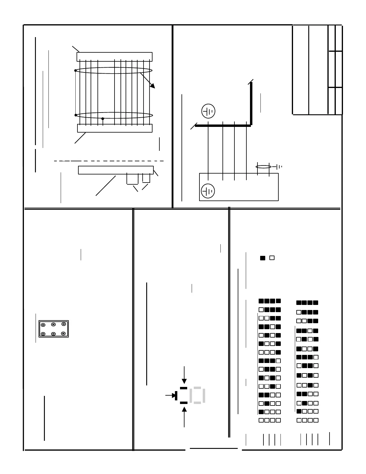
Jumpers
Dummy Plug
If the Motor is
disconnected,
the Module
will not fault
if this plug
is installed
- - - - - - - - - - - -
6FX2003-1CF12
- - - - - - - - - - - - - - -
611-A AC Servo
Feed Module
1 ( U )
2 ( V )
6 ( W )
5 ( BR2 )
4 ( BR )
U2
V2
W2
( - )
( + )
Siemens Energy & Automation
Machine Industry Business
6 / 3 / 97 A - 3 de
Interface Drawing for ;
Date
Revision
Drawn by
611-A SERVO, COMFORT VERSION
Wiring of Motor to Drive F/B Cable
Tacho, Rotor Position & Thermistor
( suggested Wire Size AWG 22 or 24 )
11
12
7
6
8
4
3
1
2
5
9
10
6FX2003-0CE12
( Motor End )
8
15
7
14
1
9
4
6
13
5
2
11
12
6FC9348-7AT
( Drive End )
NOTE: Motor to Drive connections
must be exactly as shown !
Connections for Optional (G45) Motor Mounted Brake
[24 VDC, + / - 10% - Current range 0.4 to 3.25 Amps
dependent on Motor / Brake size].
If not used, all three (3) wires should be connected to
ground.
Test Points
X
W
M
R Speed Command
T Current Command
NZ Speed Command
Alternate Input
Motor Speed
Motor Current
Reference
Common
“ X “ : Voltage @ Rated Speed ;
= 11 VDC if Tacho is rated 16.5 VDC
= 10 VDC if Tacho is rated 40 VDC
“ W “ : 10 VDC = ;
Module “ Imax ” as set in Parameter
Board by S2, Switches 2,3,4 & 5
“ M “ : Common reference for all Test Points
“ R ” = Voltage at Terminals X321 - 56 / 14
(or command inserted at “ NZ ”) .
“ T “ = 10 VDC = ( same as Test Point “ W “ )
“NZ” = Additional input for a speed command
Test Points
Ready / Fault LED Display
Parameter Board Installed
Terminal 65
Enabled
Terminal 663
Enabled
- A - Normal Status Display
- B - Fault Display ( Numeric Display; 1 . . . . 7 )
1 = I
2
T is Active
2 = Rotor Position Detector(or Cable) Fault
3 = Motor Overtemperature
4 = Tach Monitoring (or Cable) Fault
5 = I
2
T active and the Speed Controller is at
Limit ( Drive in Current Limit > 200 ms )
6 = Speed Controller is at Limit ( Drive in
Current Limit > 200 ms, without I
2
T
being active ) .
7 = Speed Controller is at Limit and the
Motor Current = 0
Tacho R
Tacho S
Tacho T
Tacho M
P15(RPG)
RPD R
RPD S
RPD T
M(Grnd.)
PTC
PTC
Page 2 / 3
Wiring of Motor to Drive Power Cable
( Wire size dependent on Motor Type )
S2(10 Bit Dip Switch) - Decoding of Switch Settings
Bit 1 = Motor Direction : If ON(as shipped), Motor Rotation CCW with + at Terminal 56(in reference to 14)
Current Limit as a % of Module Peak Current
Bit 2 =
Bit 3 =
Bit 4 =
Bit 5 =
100 85 68 61 50 46 41 39 36 34 30 29 26 24 23 = % I
Limit
Current Loop Proportional Gain (Kp I)
Bit 6 =
Bit 7 =
Bit 8 =
Bit 9 =
0.5 1 2 2.5 4 4.5 5.5 6 6.5 7.5 8 9.5 11 11.5 = Kp I
Bit 10 = If OFF(as delivered), Drive in Velocity Mode.
If ON, Drive in Current(Torque) Mode(Command to 24 & 20)
= Off
= On
NOTE: For correct grounding, the Drive end Shield
of this cable should be connected to the Connector
Shell or the M5 hole on the top of the Module.
SECTION H
 Loading...


