Siemens Energy & Automation
Machine Industry Business
6 / 10 / 96 Rev. - F de
Interface Drawing for :
Date
Revision
Drawn by
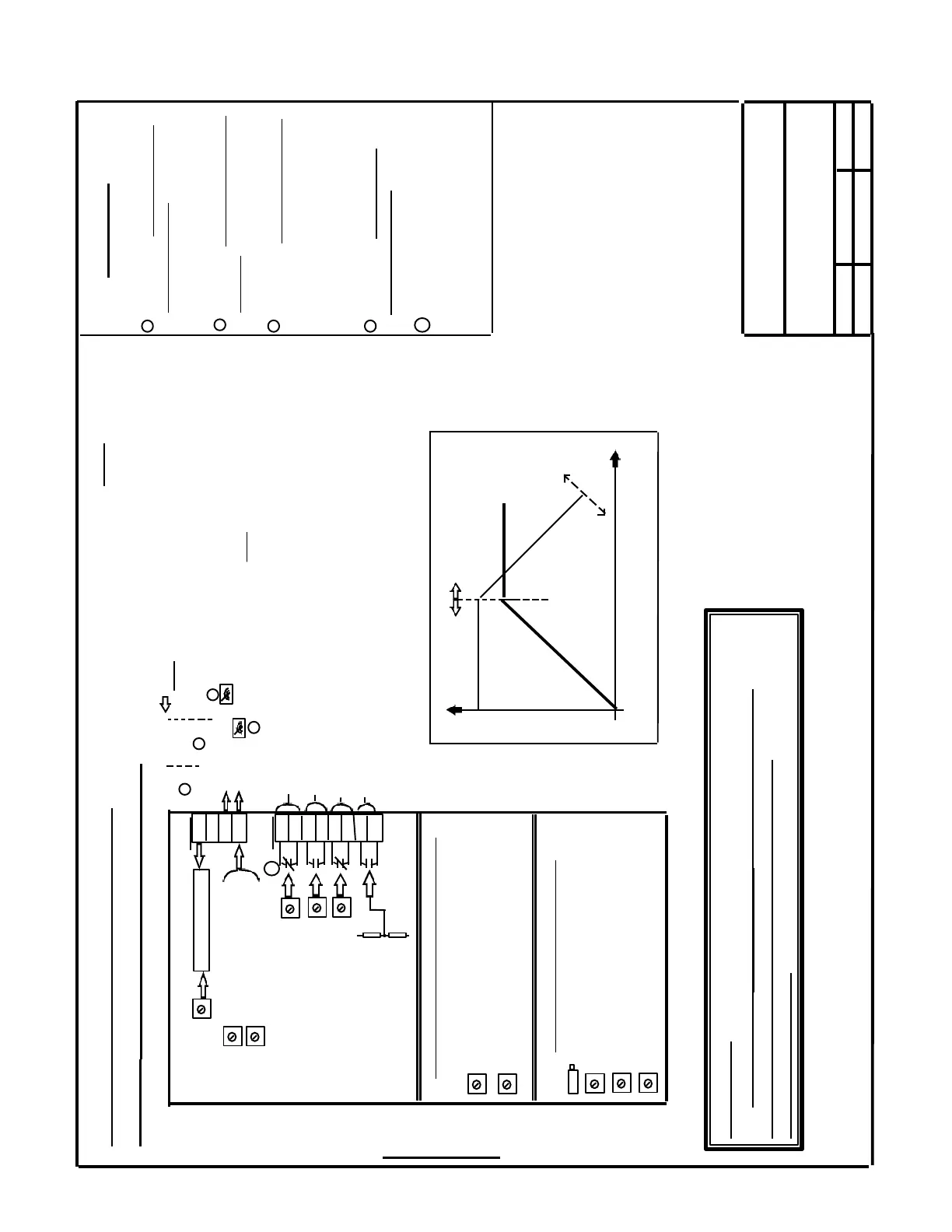
611-A Servo
Main Spindle Option ( part of Comfort
Version PCB 6SN1118- 0AA11- 0AA1 )
Built in “Main Spindle Option” Board
PCB P/N: 6SN1114 - 0AA02 - 0AA0
Iact > I x
Nact < Nmin
Nact < N x
Nact = Nset
X322
102
61
75
162 - - - - - - - - - - - - - - - - - - - - - - -
X312
R20
(Ramp Time)
110
108
115
114
216
214
127
126
“Ix” adjustment-R211
“Nmin” adjustment-R10
“Nx” adjustment-R43
R180
R179
R96 (Main Spindle - Drift [ Balance ] )
R45 ( Kp - Main Spindle Proportional Gain)
R44 ( Tn - Main Spindle Integral Gain)
R1 ( Main Spindle - RPM for Pulse Inhibit )
R906 ( Offset / Balance)
R903 ( Amplitude )
R214 ( Speed @ which Current [Torque ]
reduction starts)
R213 ( Current [ Torque ] @ maximum
Speed)
Speed Dependent Current (Torque) Limit
( Sets Constant Power Range )
“Nact = Nset”
adjustment
- -| |- - -
Term. # 102: Select Ramp Time
Adjustment Range
(open = 0.01 to 1.1 Sec.’s
(closed = 0.1 to 11 Sec.’s
Term. # 61: Select Servo / Spindle
operation (open = Spindle; closed
= Servo [“C” Axis] )
- - - - - - - -| |- - -
- - - - - - - - - - - - - - - - - - - - To I / R Module
From Feed Module
X331 , Terminal “9”
( P24 Ext. )
1
2
3
4
1
2
3
4
Term. # 75: Actual Speed output ;
As delivered, Vout = 9.45 VDC
@ Motor Rated Speed . For very
accurate requirements, Vout vs.
Motor Shaft speed must be
measured ( relationship is linear).
Term. # 162: Actual Current or
Actual Power output ( Actual
Power is factory standard )
NOTES:
Main Spindle Mode Adjustments
5
5 Contacts shown “as supplied ”
by the factory. They can be
configured “NO or NC” as
required
Ramp Generator
Speed
Torque
Power
0
0
R214
R213
Fig. 1
[ See Fig. 1]
- - - - - - -
NOTE: All external
connections are
optional ( ie; not
required for basic
operation )
Connector X141 ,
Terminal 15 (common)
Special Note: If the Servo Module contains this “Option”,
it is imperative that R4, R5 and C4(if installed) be removed
from the Parameter Board “6SN1114-0AA01-0AA0” (see section “H”)
before applying power.
SECTION I
 Loading...


