Siemens Energy & Automation
Machine Industry Business
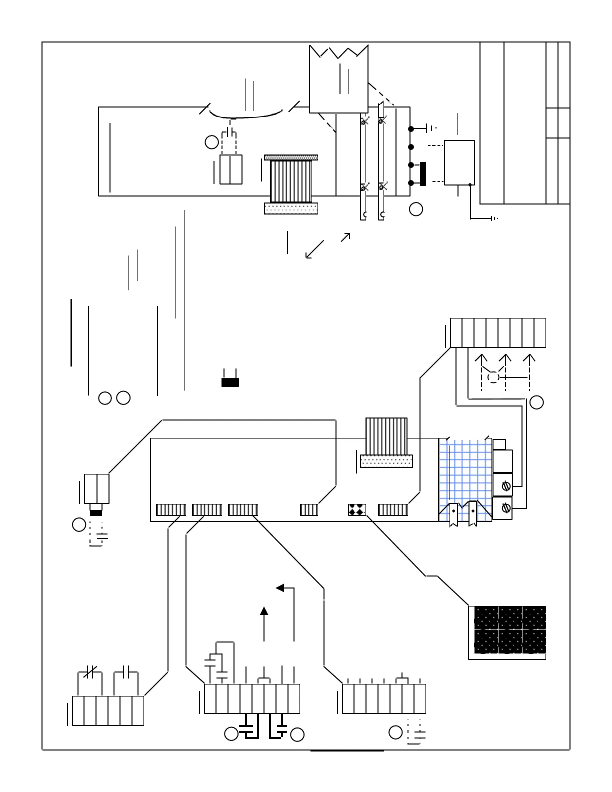
Drawing for: Interface connections
for Monitoring and Pulsed Resistor
Modules ( 611-A)
Date by Revision
6 / 10 / 96 de Rev. D
NOTES:
74
73.2
73.1
72
X111
Ready / Fault
Status Relay
Output
(250VAC / 1 Amp.
30VDC / 1Amp.)
6SN1112-...
Monitoring
Module
X121
9
64
5.3
5.2
5.1
63
9
19
FR+
FR-
Pulse Enable
Drive Enable
I
2
T & Motor
Over Temp.
Monitoring
(30V / 1 Amp.)
(Internal 24V
Supply for
Enables )
X141
7
45
44
10
15
15
R
P(+)24
P(+)15
N(-) 15
N(-) 24
M (P. S. Common )
Reset
Drive’s
Internal
Power
Supplies
LED Status and
Fault Indications
5V(Red)
Ready(Yel)
DC Link Over
Volt.(Red)
+ / - 15V(Red)
63 or 64 (Grn)
(not enabled)
Line (Red)
X181
M500
P500
2U1
2V1
2W1
X351
Ribbon
Cable
from next
module
X161
9
112
Set-Up or
Standard
Operation
To X351
of preceeding
Module
To DC Link
of preceeding
Module
6SN1113- 1AB01- 0BA0
Resistor Module
X221
50
15
(P24)
( Internal “ON” > 643 V
“off” < 618 VDC )
X151
P600
M600
( Required
connections )
1R 2R 3R PE1
Earth
Ground
For additional information on terminal definition,
use and operation see the “Planning Guide”,
Sections 3.7... and 3.8...
1
This Optional Input is used only when 400 VAC is
supplied seperately to the Power Supply (1 place)
Items shown on the left side of connectors are
external connections to be supplied by the installer
External “On”
Note: Infeed
Power Module
must
be
disabled
prior to
activating
terminal 50
Specific Notes
General Notes
Indicates Factory
supplied jumper
Optional
External
Resistor
Power Dissipation
-with out ext. resistor ;
0.3 KW Continuous
25 KW / 200 ms.
-with ext. resistor ;
1.5 KW Continuous
25 KW / 10 Sec.
NOTE: Remove Jumper
at 1R-2R when using
External Resistor !
1
P600 M600
D C Link Cover
( for connections see;
“General Wiring for
Power, Grounding and
Module Interconnection)
DC Link
Cover
Solid Line connections are required ,
Dashed Line connections are optional
( 6 places )
2
2
2
2
2
2
2
2
(6SN1113-1AA00-
0CA0)
SECTION J
(6SY9896)
(6SY9897)
(6SY9898)
(6SY9433)
(6SY9900)
(6SY9433)
 Loading...


