AL S
08.95
AL S/2-5
Siemens AG 1997 All Rights reserved 6SN1197–0AA20
SIMODRIVE 611 (PJ)
It is not possible to mechanically rotate the axis at the non–drive end of the mo-
tor. The motor should be mechanically rotated at the most accessible location
(e.g. lead screw).
Table 2-4 Radial eccentricity of the shaft to the housing axis
(referred to the cylindrical shaft ends)
Shaft height
Standard N Option R
36 0.035 mm 0.018 mm
48 (1FT5) 0.035 mm 0.018 mm
48 (1FT6/1FK6) 0.04 mm 0.021 mm
63 0.04 mm 0.021 mm
71 0.04 mm 0.021 mm
80 0.05 mm 0.025 mm
100 0.05 mm 0.025 mm
132 0.05 mm 0.025 mm
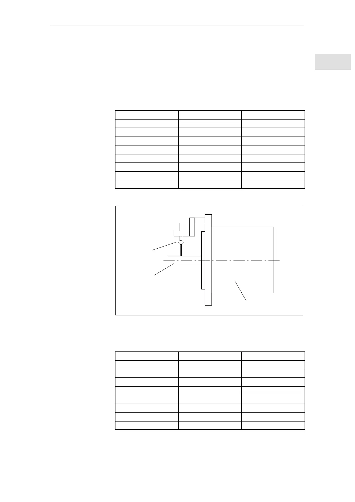
Motor shaft
Dial gauge
Motor
Check: Radial eccentricity
Fig. 2-3 Radial eccentricity check
Table 2-5 Concentricity– and axial eccentricity tolerance of the flange surface to the
shaft axis (referred to the centering diameter of the mounting flange
Shaft height
Standard N Option R
36 0.08 mm 0.04 mm
48 0.08 mm 0.04 mm
63 (1FT5) 0.08 mm 0.04 mm
63 (1FT6/1FK6) 0.1 mm 0.05 mm
71 0.1 mm 0.05 mm
80 0.1 mm 0.05 mm
100 0.1 mm 0.05 mm
132 0.125 mm 0.063 mm
Mechanically
release
Radial eccentricity,
concentricity and
axial eccentricity
(acc. to DIN 42955)
General information on AC servomotors
2.1 Definitions01.98