AL S
08.95
AL S/2-10
Siemens AG 1997 All Rights reserved 6SN1197–0AA20
SIMODRIVE 611 (PJ)
2.2 Mounted/integrated components
By mounting the motor to the flange, some of the motor power loss is dissipated
through the flange.
Mounting design which is not thermally insulating
The following mounting conditions are valid for the motor data shown:
Table 2-9 Mounting condition, non–thermally insulating mounting
Shaft height
Steel plate
width x height x thickness
Mounting surface
[m
2
]
36/48 120 x 100 x 40 0.012
63 to 132 450 x 370 x 30 0.17
The heat dissipation conditions are improved for larger mounting surfaces
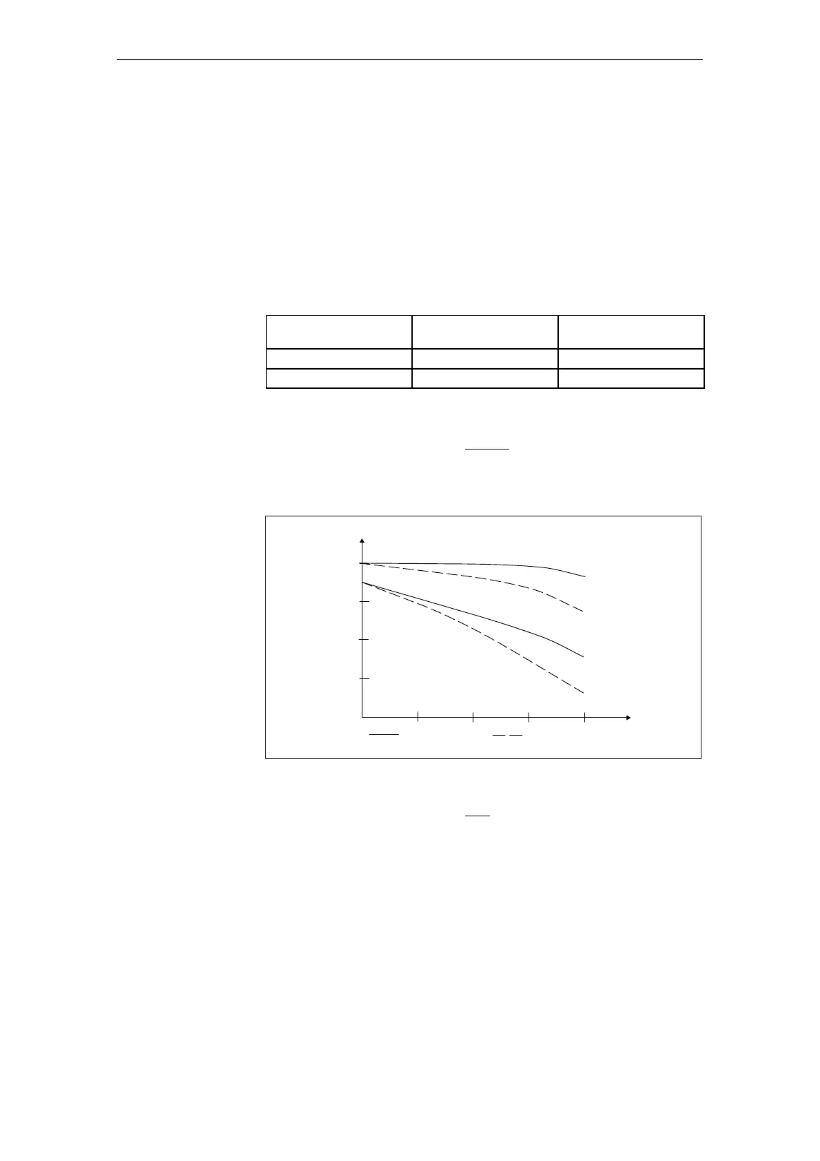
Thermally insulated mounting without additional mounted components
The motor torque must be reduced by between 5 % and 10 %. We recom-
mend to configure the system using the M
0
(60 K) values.
n [RPM]
M [Nm]
100 %
Insulated mounting
without gearbox
with gearbox
approx. 85 %
to 95 %
Non–insulated
mounting
Fig. 2-7 S1 characteristics
Thermally insulated mounting with additional mounting components
– Holding brake (integrated in the motor)
Additional torque reduction is not required
– Gearboxes
The torque must be reduced (refer to the diagram above)
Instructions on the rating plate: “Reduce rating with gearing”
Dimensioning information regarding the required motor size is provided in the
following section.
Effects of
mounting
General information on AC servomotors
2.2 Mounted/inte
rated components