3
02.98
1-51
Siemens AG 1998 All Rights reserved 6SN1197–0AA00 02.98 Edition
SIMODRIVE 611 (PJ)
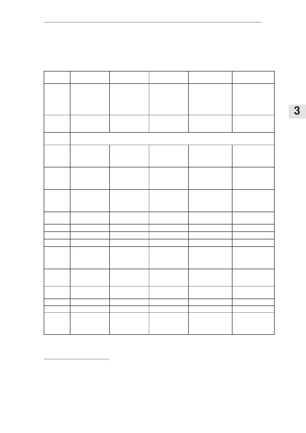
Assignment of the filter modules to the I/R modules (only
square–wave current operation)
Table 3-16
I/R module
16/21 kW
I/R module
36/47 kW
I/R module
55/71 kW
I/R module
80/104 kW
I/R module
120/156
kW
Filter com-
ponents
Filter module,
16 kW with integral
commutating reac-
tor
Filter module,
36 kW with integral
commutating reac-
tor
Filter module,
55 kW with integral
commutating reac-
tor
Two 55 kW filter mo-
dules with integrated
commutating reactor.
The filter modules are
connected in parallel.
Two 55 kW filter mo-
dules with integrated
commutating reactor.
The filter modules
are connected in pa-
rallel.
Order No.,
Filt. module
6SN1111–
0AA01–0BA1
6SN1111–
0AA01–0CA1
6SN1111–
0AA01–0DA0
2x,
6SN1111–
0AA01–0DA0
2x,
6SN1111–
0AA01–0DA0
Mounting
position
Wall– or floor mounting, refer to dimension drawings, Section 12.
A mounting bracket set is required for floor mounting.
Order No.,
bracket set
for floor
mounting
6SN1162–
0BA06–0AA0
6SN1162–
0BA06–0AA0
6SN1162–
0BA06–0AA0
2,
6SN1162–
0BA06–0AA0
2,
6SN1162–
0BA06–0AA0
Order No.,
heat barrier
for wall
mounting
6SN1162–
0BA07–0AA0
6SN1162–
0BA07–0BA0
6SN1162–
0BA07–0BA0
2,
6SN1162–
0BA07–0BA0
2,
6SN1162–
0BA07–0BA0
Order No.,
heat barrier
for floor
mounting
6SN1162–
0BA07–0AA0
6SN1162–
0BA07–0AA0
6SN1162–
0BA07–0AA0
2,
6SN1162–
0BA07–0AA0
2,
6SN1162–
0BA07–0AA0
Module
width
150 mm 250 mm 300 mm 2 x 300 mm 2 x 300 mm
Filter Filter 26 kg 40 kg 43 kg 2 x 43 kg 2 x 43 kg
I
rated
filter 30 A 67 A 103 A 150 A 225 A
P
v
filter 290 W 460 W 710 W 1220 W 1420 W
Max. con-
nection
cross–sec-
tion
16/10 mm
2
1)
PE,
potential bonding:
M5 thread
50 mm
2
PE,
potential bonding:
M8 thread
50 mm
2
PE,
potential bonding:
M8 thread
2 x 50 mm
2
PE,
potential bonding:
M8 thread
2 x 50 mm
2
PE,
potential bonding:
M8 thread
Terminals,
supply input
L1, L2, L3,
pot. bonding,
shield, PE
L1, L2, L3,
pot. bonding,
shield, PE
L1, L2, L3,
pot. bonding,
shield, PE
2 x L1, L2, L3,
Potential bonding,
screen, PE
2 x L1, L2, L3,
Potential bonding,
screen, PE
Terminals,
output
U, V, W
shield, PE
U, V, W
shield, PE
U, V, W,
shield, PE
2 x U, V, W
shield, PE
2 x U, V, W
shield, PE
I
rated
, fuse
2)
35 A 80 A 125 A 160 A 250 A
Cooling Non–ventilated Non–ventilated Non–ventilated Non–ventilated Non–ventilated
Radio inter-
ference
suppression
EN 55011
Cable–borne noise,
limit
value class A
Cable–borne noise,
limit
value class A
Cable–borne noise,
limit
value class A
Cable–borne noise, li-
mit
value class A
Cable–borne noise,
limit
value class A
The filter modules can be mounted horizontally and vertically (line at the bottom,
load at the top).
1)The 1st number is for cable lugs, the 2nd number is valid for finely–stranded conductors without endsleeves.
2)The fuse used must have this rated current. Refer to Table 3-10 for recommended fuses.
Mounting position
of the filter
modules
3.5.1 Assignment of the filter modules to the I/R modules