3
02.98
1-60
Siemens AG 1998 All Rights reserved 6SN1197–0AA00 02.98 Edition
SIMODRIVE 611 (PJ)
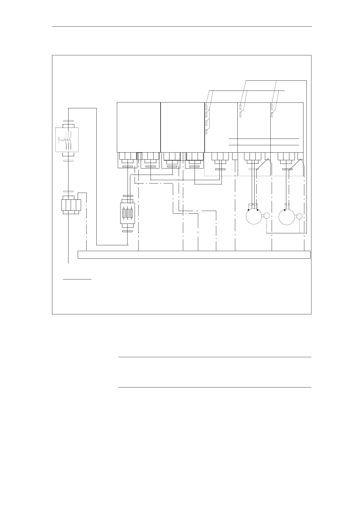
Cabinet mounting panel
Connect the PE – bar through the largest possible surface area to the cabinet mounting panel
1)
I/R
module
2)
MSD
module
2)
FD
module
P600
M600
2)
M
G
M
G
Encoder cables
Function
cables
Filter module
2) 2)
Filter module
2)
1)
2)
1)
1)
1)
1)Shield connection, connected through the largest possible surface area with the cabinet mounting panel.
3)The potential bonding conductor is an additional protection so that no inadmissibly high contact voltages can
occur at the filter module.
2)Shield connection at the module–specific connecting panel.
Incoming terminals
Main switch
Fuses
Supply
L2
L3L1
PE
L2L1 L3
PE PE PE
VU W
L2L1 L3 VU W
V1U1 W1 V2U2 W2 V2U2 W2
PE
PE
Figure 3-15Connecting diagram for two filter modules, connected in parallel for 80 kW and 120 kW I/R modules for
square–wave current applications
!
Important
The filter modules must be connected up with the same phase sequence if they
are connected in parallel.
J
3.5.5 Installation and connection regulations