3
02.98
1-59
Siemens AG 1998 All Rights reserved 6SN1197–0AA00 02.98 Edition
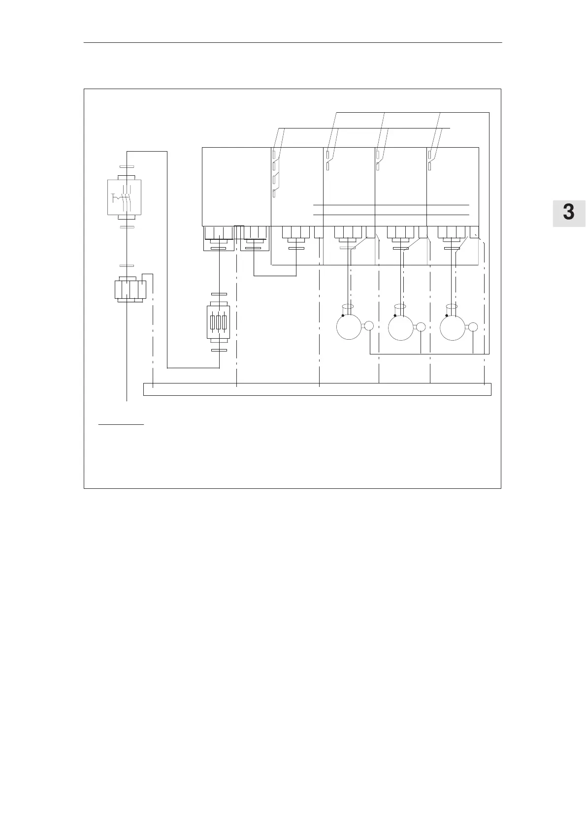
SIMODRIVE 611 (PJ)
G
GG
L2
L3L1
PE
Filter module I/R
module
2)
MSD
module
2)
FD
module
2)
FD
module
2)
P600
M600
Connect the PE – bar through the largest possible surface area to the cabinet mounting panel
2)
M
M M
Encoder cables
Function
cables
1)
1)
2)
Cabinet mounting panel
1)
1)
1)
Supply
Incoming terminals
Main switch
1)Shield connection, connected through the largest possible surface area with the cabinet mounting panel.
2)Shield connection at the module–specific connecting panel.
PE PE PE PE
V2U2 W2V2U2 W2V2U2 W2V1U1 W1
VU W
L2L1 L3
Fuses
PE
Figure 3-14Connecting diagram for filter modules for the I/R modules 16 kW, 36 kW and 55 kW for square–wave current
operation
3.5.5 Installation and connection regulations