3
02.98
1-58
Siemens AG 1998 All Rights reserved 6SN1197–0AA00 02.98 Edition
SIMODRIVE 611 (PJ)
G
G
Function
cables
Connect the PE – bar through the largest possible surface area to the cabinet mounting panel
Cabinet mounting panel
I/R module
or
UE module
28kW
2)
MSD module
2)
FD module
P600
M600
2)
M
M
1)
1)
1)
Supply
1)Shield connection, connected through the largest possible surface area with the cabinet mounting panel.
2)Shield connection at the module–specific connecting plate
3)For the permissible commutating reactors for I/R module, sinusoidal operation, refer to Sections 3.4.2 and 3.1
Permissible commutating reactor for 28kW UE module, refer to Section 3.4.2
Encoder cables
1)
1)
Incoming terminals
Main switch
PE PE
PE
L2
L3L1
PE
V1U1 W1 V2U2 W2 V2U2 W2
Filter
L1L2
L3
L1L2
L3
LOAD
1U1
1V1
1W1
1U2
1V2
1W2
HF comm.
reactor 3)
1)
1)
1)
1)
Fuses
PE LINE
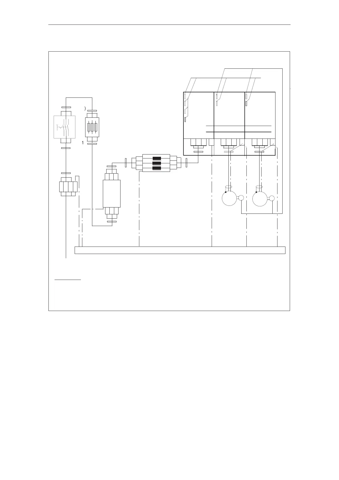
Figure 3-13Connecting diagram for the line filter for I/R modules, 16kW to 120kW
The connecting diagram is also valid for UE–28kW, but 6–pulse square–wave current flows as a result of the
uncontrolled infeed.
3.5.5 Installation and connection regulations