7
02.98
1-75
Siemens AG 1998 All Rights reserved 6SN1197–0AA00 02.98 Edition
SIMODRIVE 611 (PJ)
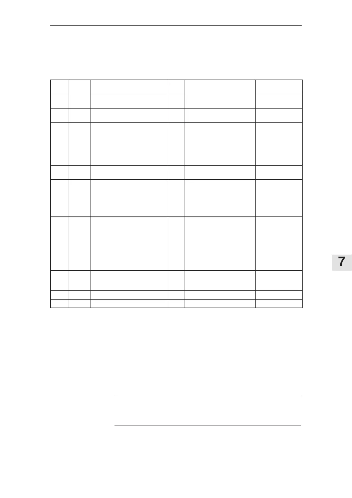
Interface overview, feed control, user–friendly interface
Table 7-2
Term.
No.
Desig. Function
Type
1)
Typ. voltage/ limit values Max. cross–sect.
56
14
X321
X321
Speed setpoint 1
Differential input
2)
I
I
0V... ± 10V 1.5 mm
2
1.5 mm
2
AS1
AS2
X331
X331
Checkback signal contact
Relay, start inhibit
NC Max. 250V
AC
/1A. 30 V
DC
/2A 1.5 mm
2
1.5 mm
2
663
9
65
9
22
23
X331
X331
X331
X331
X331
X331
Pulse enable
3)
Enable voltage
3)6)
Controller enable
3)
Enable voltage
3)6)
Select int. fixed setpoint 1
3)
/
current–controlled operation
Select int. fixed setpoint 2
3)
I
O
I
O
I
I
+21...30 V
+24 V
+13...30 V
+24 V
+13...30 V
+13...30 V
1.5 mm
2
1.5 mm
2
1.5 mm
2
1.5 mm
2
1.5 mm
2
1.5 mm
2
20
24
X331
X331
Speed setpoint
2)
/ current setpoint
(differential input)
I
I
0V...±10 V
(340 µs smoothing)
1.5 mm
2
1.5 mm
2
96
5)
44
5)
6
5)
258
5)
16
5)
X331
X331
X331
X331
X331
Current setpoint limiting
Electronics voltage
Integrator inhibit, speed controller
Current setpoint (master/slave)
Norm. current actual value
I
O
I
I/O
O
0...±30 V
–15 V/10 mA
+13...30 V
0 V...±10 V
0 V...±10 V
1.5 mm
2
1.5 mm
2
1.5 mm
2
1.5 mm
2
1.5 mm
2
289
288
290
291
293
294
296
297
299
X341
X341
X341
X341
X341
X341
X341
X341
X341
Relay signals, center contact
Speed controller at its endstop
I
2
t monitoring
Motor overtemperature
Tachometer/rotor position enc. fault
I
NO
NC
NO
NC
NO
NC
NO
NC
4)
Max. 30 V/1 A
Max. 30 V/1 A
Max. 30 V/1 A
Max. 30 V/1 A
Max. 30 V/1 A
Max. 30 V/1 A
Max. 30 V/1 A
Max. 30 V/1 A
1.5 mm
2
1.5 mm
2
1.5 mm
2
1.5 mm
2
1.5 mm
2
1.5 mm
2
1.5 mm
2
1.5 mm
2
1.5 mm
2
672
673
674
X341
X341
X341
Ready/fault signal
NO
I
NC
30 V/1 A
4)
30 V/1 A
30 V/1 A
1.5 mm
2
1.5 mm
2
1.5 mm
2
X311 Motor encoder
X151 Equipment bus
_________
1) I=input; O=output; NC=NC contact; NO=NO contact (for signal NO=high/NC=low)
2) Differential input reference point
The common mode range of the differential input is24 V with respect to PE potential and may not
be exceeded.
3) Reference ground, terminal 19 NE/monitoring module (this may not be connected with the general reference
ground, terminal 15)
4) Voltages referred to PE potential
5) Terminal 15 on the NE module is the reference ground
6) Refer to p.1-37
Note
The drive shuts down and the pulses inhibited after approx. 4 s when the ”heat-
sink overtemperature” switch responds.
7.1.2 Interface overview, feed control, user–friendly interface