7
02.98
1-78
Siemens AG 1998 All Rights reserved 6SN1197–0AA00 02.98 Edition
SIMODRIVE 611 (PJ)
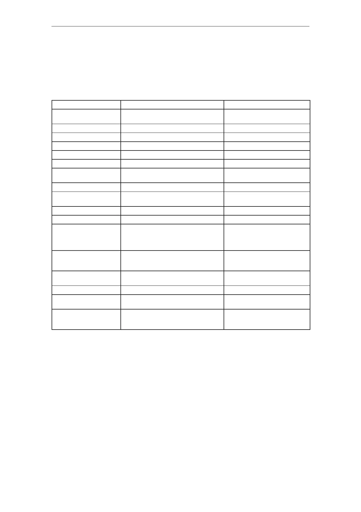
Table 7-3
Parameter
Value range Setting elements
Limit value stages
NC/NO contacts
The relay outputs of the limit value stages can
be defined as NC or NO contacts
0 Ω resistors
|I
act
| > I
X
terminals 110/108 4.5 %...100 % Pot. R211
| n
act
| < n
min
terminals 115/114 0.3 %...1.7 % of n
max
Pot. R10
| n
act
| < n
X
terminals 216/214 3 %...100 % of n
max
Pot. R43
n
set
= n
set*
terminals 127/126 n
set
difference < 20 mV Resistor R179
n < n
off
0.3 %...1.7 % of n
max
Pot. R1
Ramp–function generator via
terminals 56/14
10 ms...1.1 s
0.1 s...11 s (changeover 1:10)
Potentiometer R20
terminal 102
Tracking Active/inactive R270
Drift (main spindle drive ope-
ration)
–30 mV...+30 mV (referred to n
set
) Pot. R96
Proportional gain Reduce Kp to 0 %...95 % Pot. R45 + parameter board R25
Integral action time Extend T
N
to 100 %...1500 % Pot. R44 + parameter board R35
Torque limiting Start of constant power 23 %...70 % n
max
Deviation –20 %...+20 % n
max
Constant limiting 10 %...100 % I
max
Speed–dependent limiting 1 %...85 % I
max
Pot. R214
Pot. R213
Resistor R76
Pot. R225
Changeover speed
Main spindle drive ” C–axis
operation
0 %...100 % n
max
Resistor R77, R78
Select C axis operation, termi-
nal 61
10 V setpoint at terminals 24/20 1/10 n
max
of MSD operation
Speed actual value image Normalized n
rated
corresponds to +10 V Terminal 75
Current actual value image Normalized I
actN
= 10 V Terminal 162 if R160 = 1 k,
R207 = open
Power image Factor 1...3 Resistor R903
Terminal 162 if R160 = open,
R207 = 1 k
Function overview
and settings on the
MSD option
7.1.3 Option board, main spindle functions