Motor components and options
4.2 Options
1FK2 synchronous motors for SINAMICS S120
46 Configuration Manual, 06/2019, A5E46927724B AB
The following table contains technical specifications of the holding brakes:
Note
The following specifications apply to control with 24
V DC.
Maximum
permissible
single operat-
ing energy
2)
Total operat-
ing energy
(service life)
For spring-loaded brake
For permanent-magnet brake
1FK2❑08-3 19 12 0.8 100 40 2000 1800
1FK2❑08-4
32 17 0.9 200 60 4800 2400
1FK2❑10-4
55 26 1.0 220 60 8700 3800
Valid for direct connection to S120 and internal switching. For external brake switching, a varistor has to be used.
Maximum three EMERGENCY STOP operations in sequence, maximum 25% of all the emergency stops as high ener-
Note
If the brake is switched in two stages (two clicks), the first switching point is decisive for
opening and the second for closing.
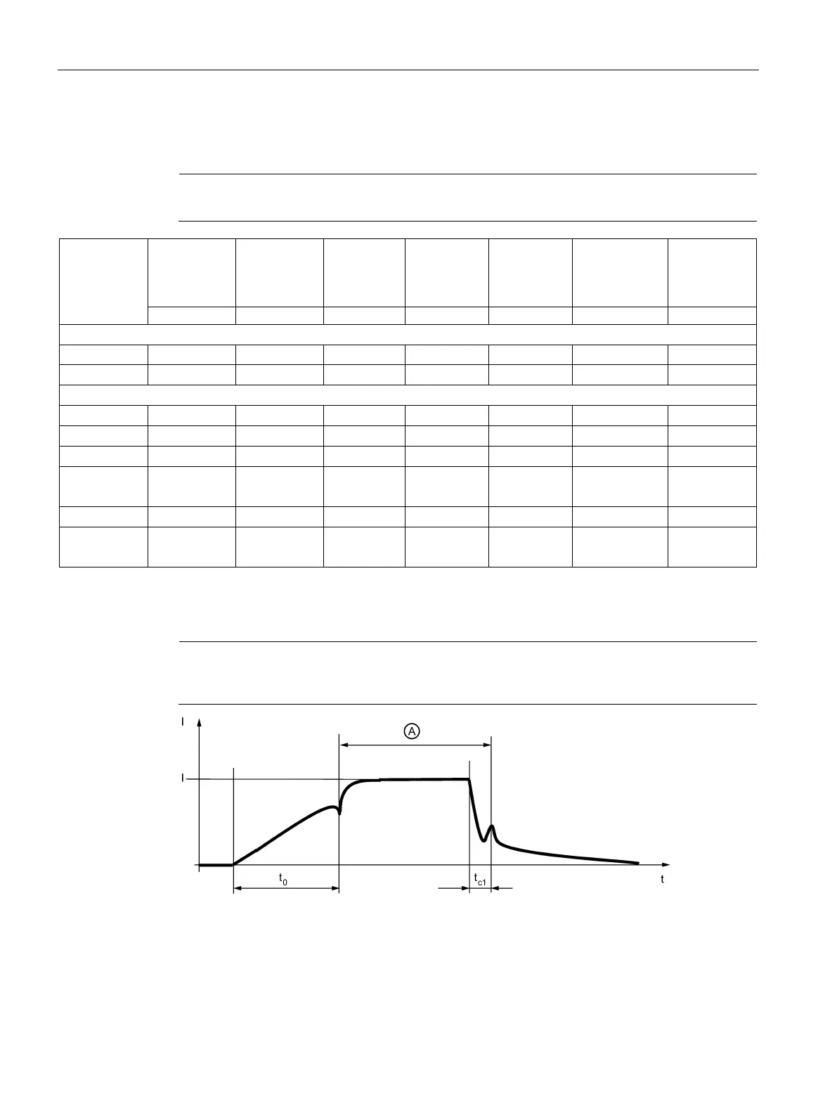
Figure 4-1 Time-related terminologzy for braking operation