Description of the motors
2.6 Mounting and options
1FK7 G2 synchronous motors
42 Operating Instructions, 05/2021, A5E50907562B AA
Function and technical data
• Angular measuring system for commutation
• Speed actual value sensing
• Indirect incremental measuring system for the position control loop
Table 2- 11 Technical data, resolver without DRIVE-CLiQ interface
Excitation voltage rms, excita-
tion frequency
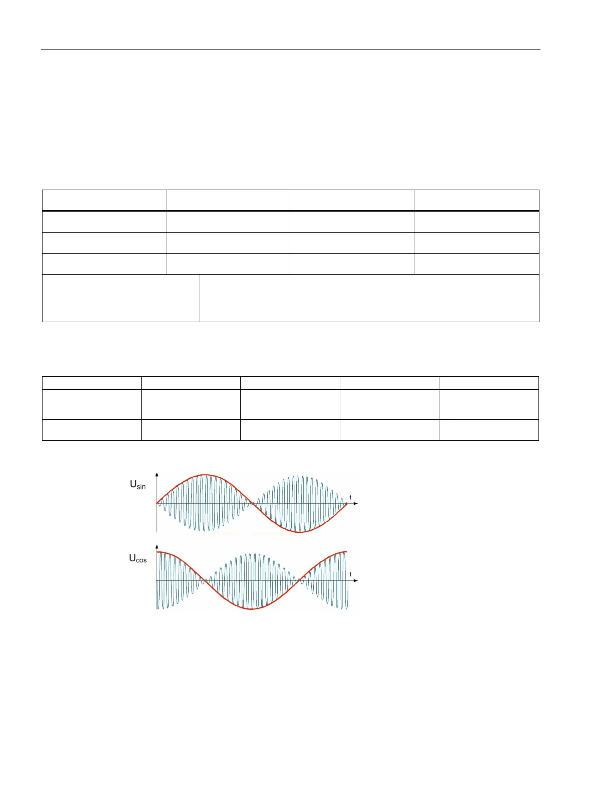
Calculation of the output signals
Transformation ratio Ü = 0.5 ± 5 %
USinusoidal track = Ü • UExcitation • sin α
U
Cosinusoidal track = Ü • UExcitation • cos α
α = arctan (USinusoidal track / UCosinusoidal track)
Table 2- 12 Technical data, resolver with DRIVE-CLiQ interface
Resolver 15-bit resolution
32768, internal, multi-
for 6-pole and 8-pole 240"
Resolver 14-bit resolution
16384, internal, 2-pole
Figure 2-6 Output signals, resolver