Mounting
4.4 Mounting conditions
1FK7 G2 synchronous motors
58 Operating Instructions, 05/2021, A5E50907562B AA
4.4 Mounting conditions
4.4.1 Natural cooling
Note the specifications on thermally non-insulated mounting and on thermally insulated
mounting.
enough heat is dissipated, a minimum clearance to adjacent components of 100
mm must be kept free on three side surfaces.
• Mount the motor in such a way that sufficient clearance is provided for heat dissipation.
The motor ratings apply in an ambient temperature of 40° C (104° F). If the ambient
temperature exceeds 40° C (104° F), you must adjust the torque and power of the motor
accordingly.
• Adjust the torque or the power of the motor at the converter based on the table in
Chapter "Derating factors (Page 27)."
Follow the Operating Instructions of the converter.
Non-thermally insulated mounting
Observe the following mounting conditions for the specified motor data:
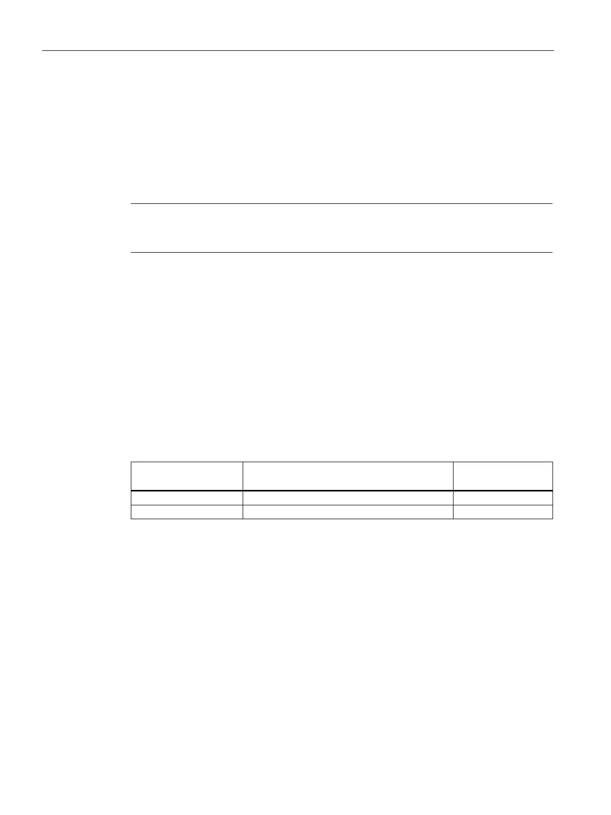
Table 4- 3 Non-thermally insulated mounting conditions
Shaft height Steel plate, width x height x thickness in mm
Mounting surface in
2
For larger mounting surfaces, the heat dissipation conditions improve.
Thermally insulated mounting without additional mounted components
For non-ventilated motors, the motor torque must be reduced by between 5% and 10%.
Configure the motor using the M
0 (60 K) values. As the speed increases, the reduction factor
rises, see figure "Effect of the mounting conditions on the S1 characteristic curve".
Thermally insulated mounting with additional mounted components
• Holding brake (integrated in the motor):
No additional torque reduction required
• Gearboxes:
The torque must be reduced. See figure "Effect of the mounting conditions on the S1
characteristic curve"