EasyManua.ls Logo

Siemens SIMOTICS S-1FK7 - Design of Signal Connectors

Siemens SIMOTICS S-1FK7
134 pages
Print Icon
To Next Page IconTo Next Page
To Previous Page IconTo Previous Page
Loading...
Connecting
5.4 System integration
1FK7 G2 synchronous motors
94 Operating Instructions, 05/2021, A5E50907562B AA
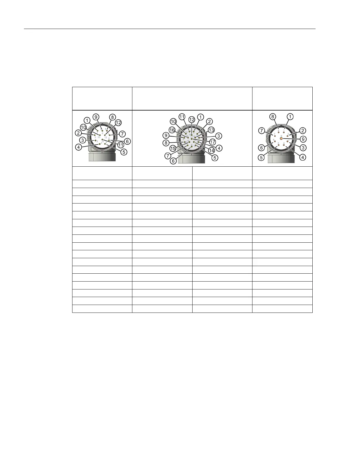
5.4.6.4 Design of signal connectors
Pin assignment of the signal connector without DRIVE-CLiQ (encoder connection)
Pin assignment, M23
signal connector, 12-
pole,
Pin assignment, M23 signal connector, 17-pole,
Pin assignment, M23
signal connector, 9-
pole
Resolvers
Incremental encoder
sin/cos 1 Vpp
Absolute encoder with
EnDat 2.1
Absolute encoder with
EnDat 2.2
1 = S2
1 = Α
1 = Α
1 = clock
2 = S4
2 = A*
2 = A*
2 = clock*
3 = not connected
3 = R
3 = data
3 = UP
4 = not connected
4 = D*
4 = not connected
4 = 0 V
5 = not connected
5 = C
5 = clock
5 = data
6 = not connected*
6 = C*
6 = not connected
6 = data*
7 = R2
7 = M encoder
7 = M encoder
7 = UP sensor
8 = +1R1
8 = +1R1
8 = +1R1
8 = 0 V sensor
9 = -1R2
9 = -1R2
9 = -1R2
9 = not connected
10 = R1
10 = P encoder
10 = P encoder
11 = S1
11 = B
11 = B
12 = S3
12 = B*
12 = B*
13 = R*
13 = data*
14 = D
14 = clock*
15 = M sense
15 = M sense
16 = P sense
16 = P sense
17 = not connected
17 = not connected

Table of Contents

Related product manuals