Connecting
5.4 System integration
1FK7 G2 synchronous motors
80 Operating Instructions, 05/2021, A5E50907562B AA
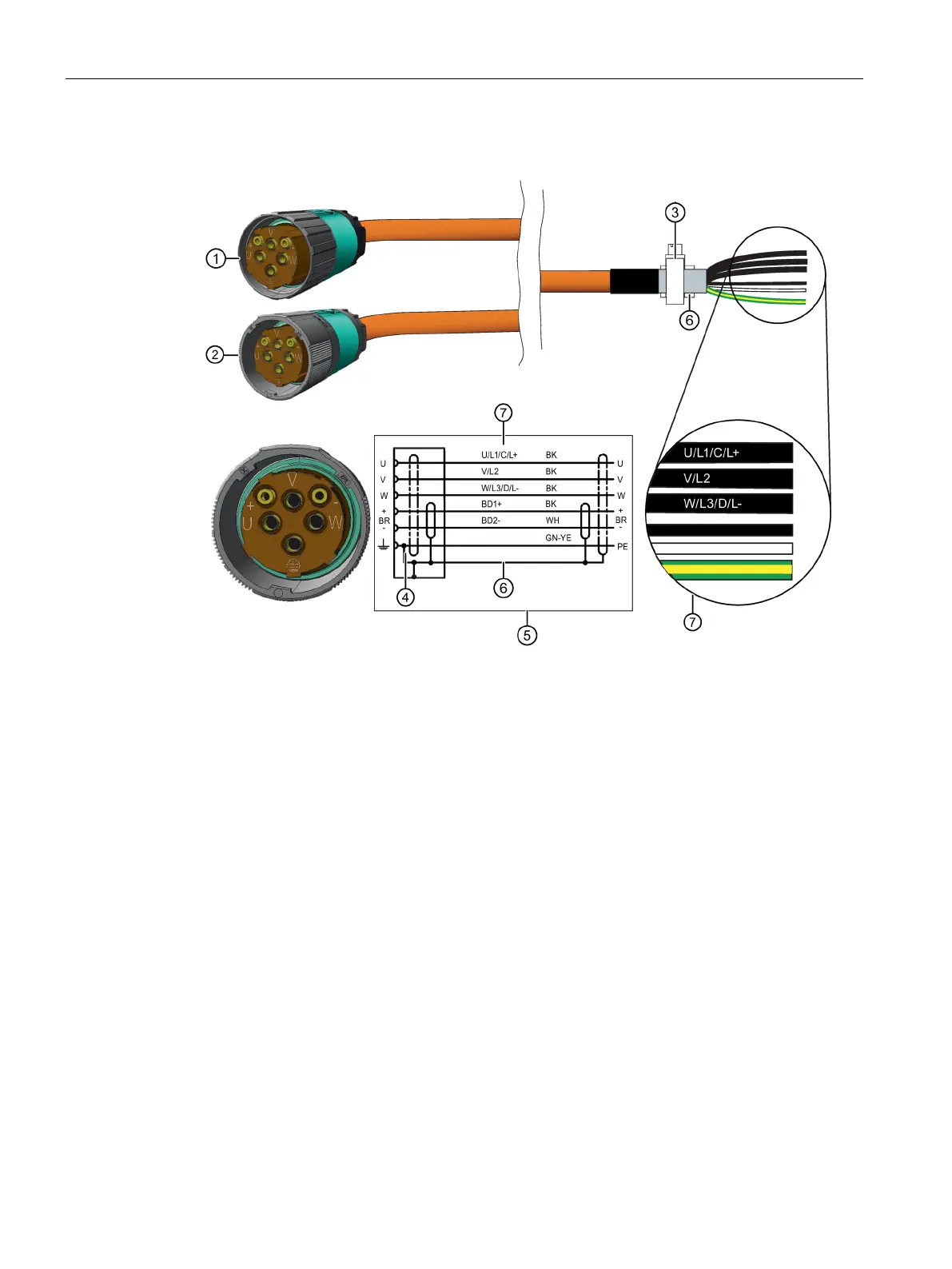
For M40 connector
SPEED CONNECT connector, M40
Terminal for the cable shield
7 Conductor designation:
U; V; W = power cables, each cable separately shielded
BD1+ and BD2- = brake cable without lettering, 1.5 mm
2
, shared shield
PE = protective conductor
• Connect the shield at both ends at the motor and at the converter.
• Keep unshielded cable ends as short as possible.
• Establish the connection through a larger surface area so that high-frequency currents are
suitably discharged. Establish a 360° connection at the converter and at the motor, for
instance using EMC cable glands at the cable entries.