Connecting
5.4 System integration
1FK7 G2 synchronous motors
84 Operating Instructions, 05/2021, A5E50907562B AA
Note
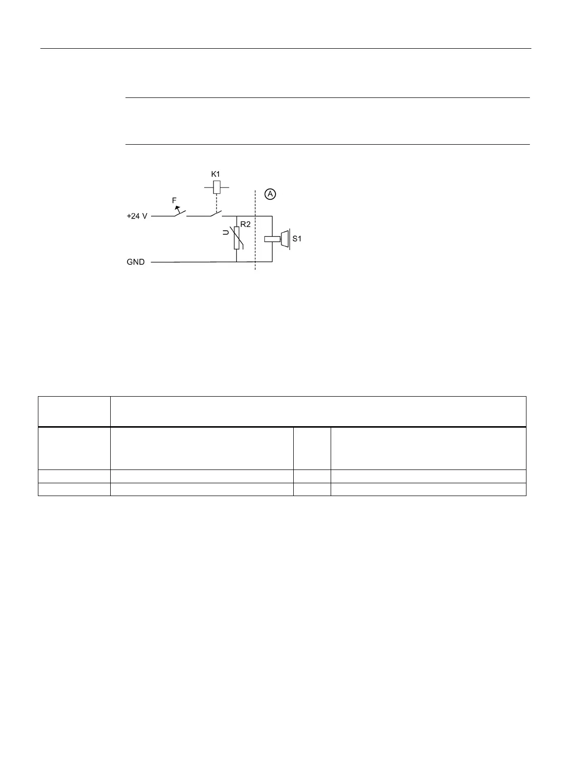
Integrate a protective circuit into the incoming cable. In this way, you avoid switching
overvoltages and possible influence of the installation environment. See the figure below
Figure 5-5 Suggested circuit for the external power supply with protective circuit
Table 5- 3 Example: Electrical components for the suggested circuit
Electrical
Examples
3RV10 circuit-breaker with current paths
connected in series (if required with mount-
ed auxiliary contact 3RV1901 to provide a
feedback signal for the drive).
Miniature circuit-breaker 5SX21 (if required with
mounted auxiliary contact to provide a feedback
signal for the drive).
Auxiliary contactor 3RH11
Varistor SIOVS14K30 (EPCOS)