Connecting
5.4 System integration
1FK7 G2 synchronous motors
90 Operating Instructions, 05/2021, A5E50907562B AA
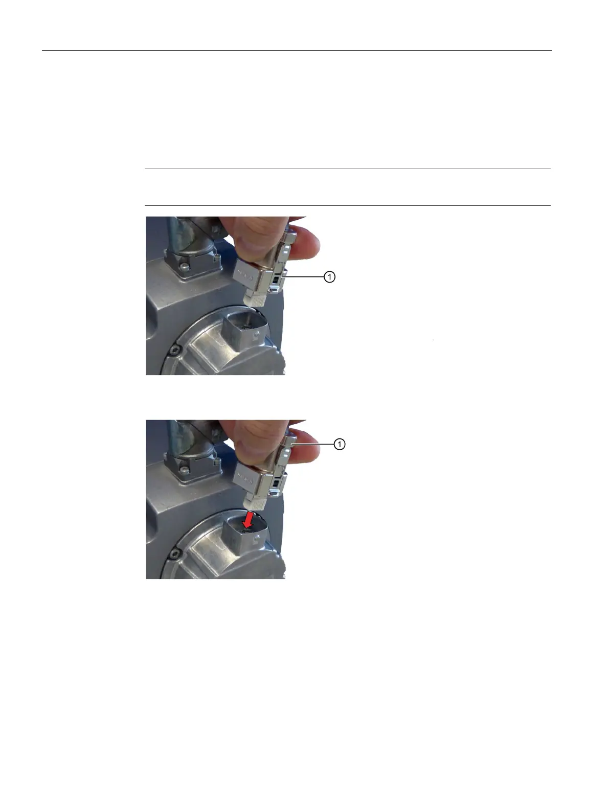
Insertion
Procedure
1. Check whether the locking ring of the connector is in the "locked" position.
If not, turn the locking ring clockwise into the "locked" position.
Note
In the "locked" position, the tabs are flush against the connector.
Locking ring in the "locked" position
2. Insert the connector into the RJ45 socket of the Sensor Module.
The locking ring remains in the "locked" position.
3. Check that the two tabs are engaged in both latches on the socket and that the connector
cannot be pulled out.