For connector size M23
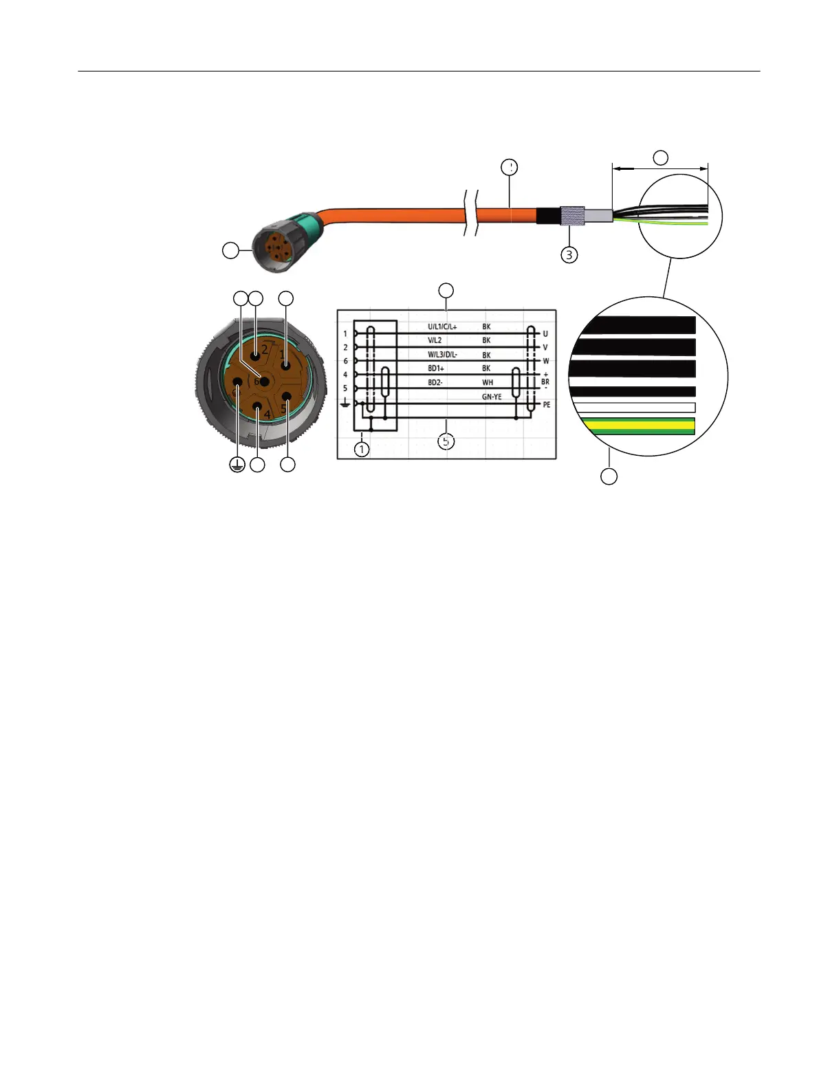
1 SPEED CONNECT connector, size M23
2 MOTION CONNECT cable
3 Cable shield
4 Connection diagram
U; V; W = power cables, 1.5mm
2
or 2.5mm
2
, each cable is separately shielded
BD1+ and BD2- = brake cable without lettering, 1.5mm
2
, shielded together
PE = protective conductor
5 Cable shield
6 Conductor designations
7 The length of the cable ends depends on the converter selected.
For connector size M40
Connecting
7.3System integration
SIMOTICS S-1FT2 synchronous motors for SINAMICS S120
Operating Instructions, 12/2023, A5E50610821B AF 87