Example 1:
●
Measuring input input is only to measure positive edges.
● 6 negative and 5 positive edges occur in cycle n.
● 2 positive edges are measured
Result: The number of lost positive edges is 3.
Example 2:
● Measuring input input is to measure any edges.
● 11 edges occur in cycle n.
● 2 edges are measured
Result: 7 lost edges are signaled; 2 further edges cannot be recorded due to the limitation of
the counter to 7 in the module.
Evaluation in the user program
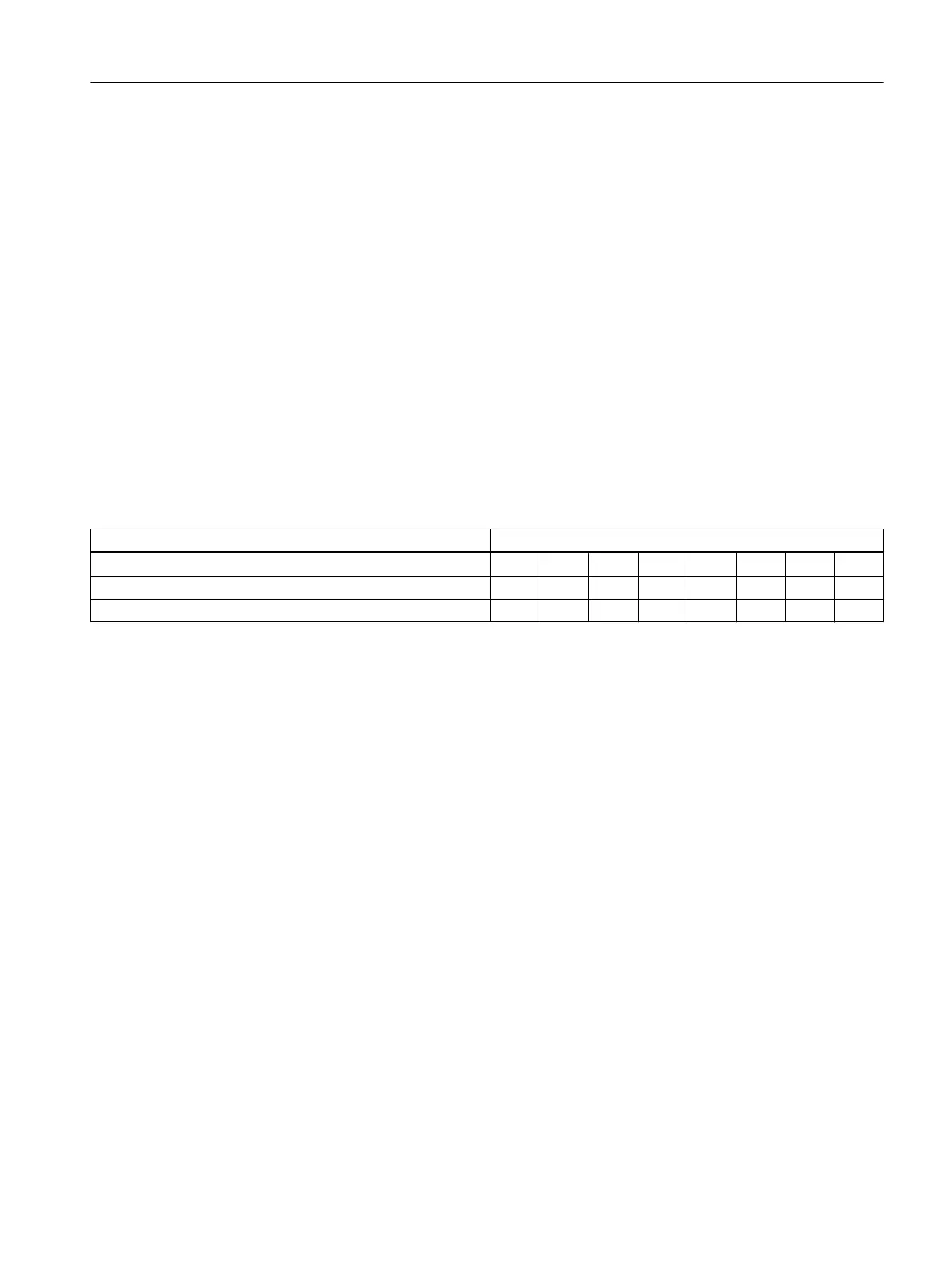
In eveluation of the LEC, ensure that the edge counter only fills 3 bits of the LEC byte in each
case. The non-relevant bits have to be masked in this way.
Lost edge counter Relevant bits in the LEC byte
7 6 5 4 3 2 1 0
for I/O channel 1 / 3 / 5 / 7 x x x
for I/O channel 0 / 2 / 4 / 6 x x x
Program example
// lec_1 : IO variable in the SCOUT, symbolically interconnected
with LEC measuring input 1 (type byte)
//
lec_2 : IO variable in the SCOUT, symbolically interconnected with
LEC measuring input 2 (type byte)
VAR
LecMeasuringInput1 : BYTE;
LecMeasuringInput2 : BYTE;
END_VAR
LecMeasuringInput1:= (lec_1 AND 16#07); // even channel
LecMeasuringInput2:= SHR((lec_2 AND 16#70),4); // odd channel
Commissioning (software)
7.13 Configuration of the technology objects and I/O variables
SIMOTION D4x5-2
Commissioning and Hardware Installation Manual, 03/2018, A5E33441636B 293