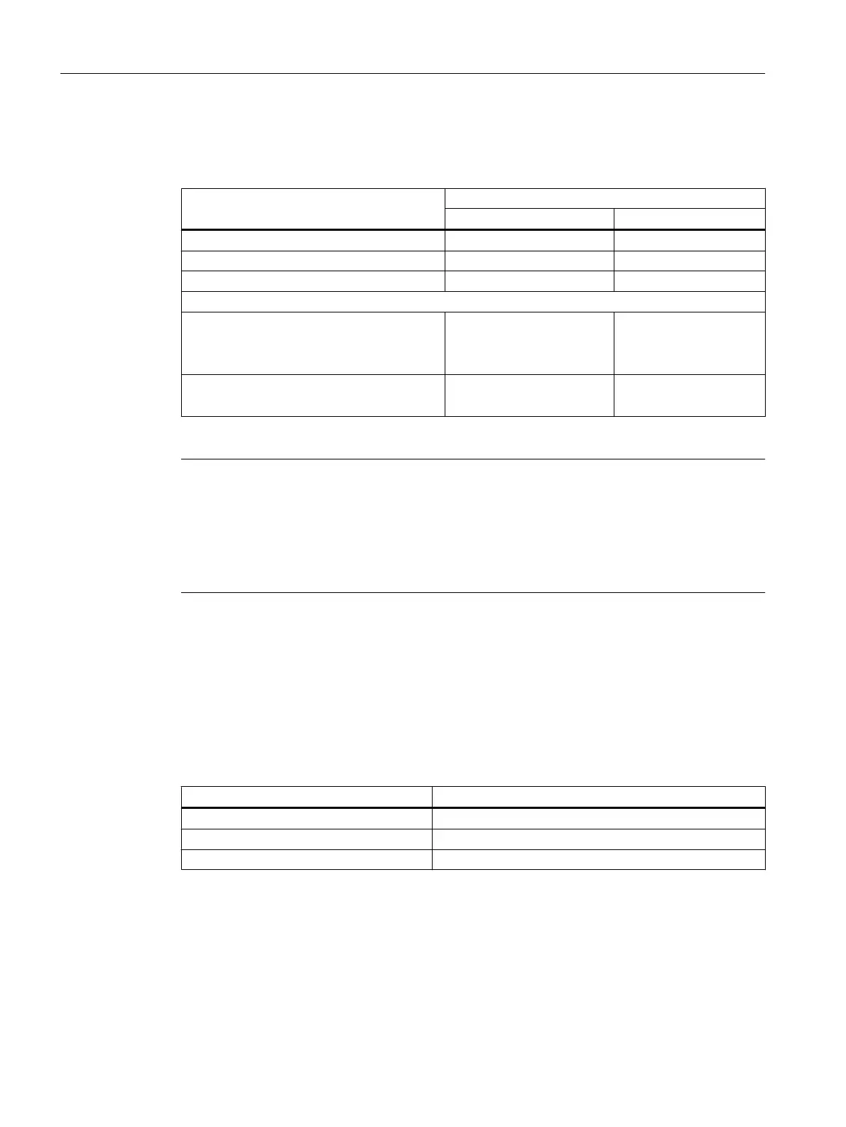
The table below lists the combination possibilities for the C230-2/C240.
Table 4-16 Combination possibilities for the C230-2/C240
Application Axis channel
Output (X2) Input (X3 to X6)
Position axis x x
Drive axis x -
External encoder - x
Also for C240:
Standard output (I/O variables)
● Analog output (PQW)
● Digital output (PQ)
x
x
-
-
Standard input (I/O variables)
1)
● Counter input (PIW)
-
x
1)
The incremental encoder used must not have a zero pulse
Note
A standard output and a drive cannot be used simultaneously on one axis channel.
The input (X3 to X6) used as a counter input cannot be used simultaneously as an encoder
input.
When a project is created and when a project is downloaded, a consistency check of the
permitted combinations per axis channel is automatically performed.
This results in the following possibilities in the application for the C240, for example:
● Configuration of hydraulic axes on the onboard resources of the C240
● Use of unassigned axis channels of the C240 as I/O variable for the user program
● Use of the analog outputs of the C240 as unassigned process outputs
Note: The resolution and the characteristic curve of the analog output of the C240 differ
from those of a SIMATIC S7 controller. The following table lists the digital values and their
associated analog values (characteristic curve).
Digital value (WORD data type) Analog value
16#7FFF ≙ 32767 +10 V
16#0000 ≙ 0 0 V
16#8000 ≙ 32768 -10 V
See also
Connecting the drive units (Page 102)
Interfaces
4.7 Possible uses of onboard drive and measuring system interface in the application (C230-2, C240)
SIMOTION C
66 Operating Instructions, 11/2016, A5E33441428B