Note: The SIMOTION C240 / C240 PN does not contain any firmware.
The micro memory card for the SIMOTION C240 / C240 PN can be used to save the
SIMOTION Kernel.
The micro memory card is also needed to save the technology packages and user data
(programs, configuration data, parameterizations).
CAUTION
The micro memory card may only be inserted or removed when the control unit is
disconnected from the power supply.
Memory module slot
The micro memory card is inserted in the memory module slot.
3.2 Display elements
LED displays
The following LED displays are on the front panel of the SIMOTION C. This table describes
the LEDs and their function.
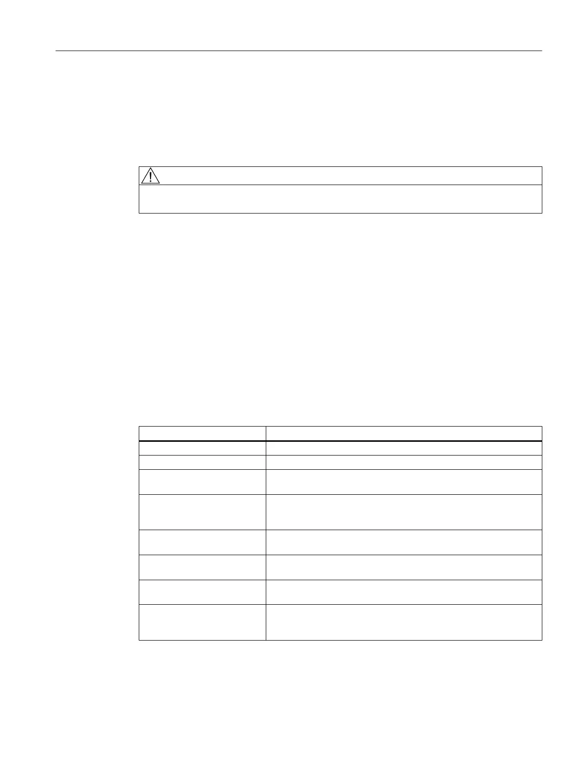
Table 3-2 Status and error displays
LED Meaning
SF (red) This LED indicates a fault on the SIMOTION C.
5 VDC (green) This LED indicates that the power supply for the electronics is ready.
RUN (green) -
SIMOTION C in RUN mode
This LED indicates that the user program is running.
STOPU (yellow) -
SIMOTION C in STOP user
program mode
This LED indicates that the technology packages (for example, syn‐
chronous operation and cam) are active. The user program is not ac‐
tive.
STOP (yellow) -
SIMOTION C in STOP mode
This LED indicates that no user program is running. The technology
packages are not active.
BUS1F (red) -
Group fault
This LED indicates a fault on the SIMOTION C PROFIBUS DP1 inter‐
face (X8).
BUS2F (red) -
Group fault
This LED indicates a fault on the SIMOTION C PROFIBUS DP2/MPI
interface (X9).
Q0 to Q7 , I0 to I11 ,
B1 to B4, M1, M2 (green) -
Digital inputs/digital outputs
These LEDs show the status of the digital inputs/outputs.
Operator control (hardware)
3.2 Display elements
SIMOTION C
Operating Instructions, 11/2016, A5E33441428B 39