The following LED displays are arranged the front cover of the SIMOTION C240 PN. This table
describes the LEDs and their function.
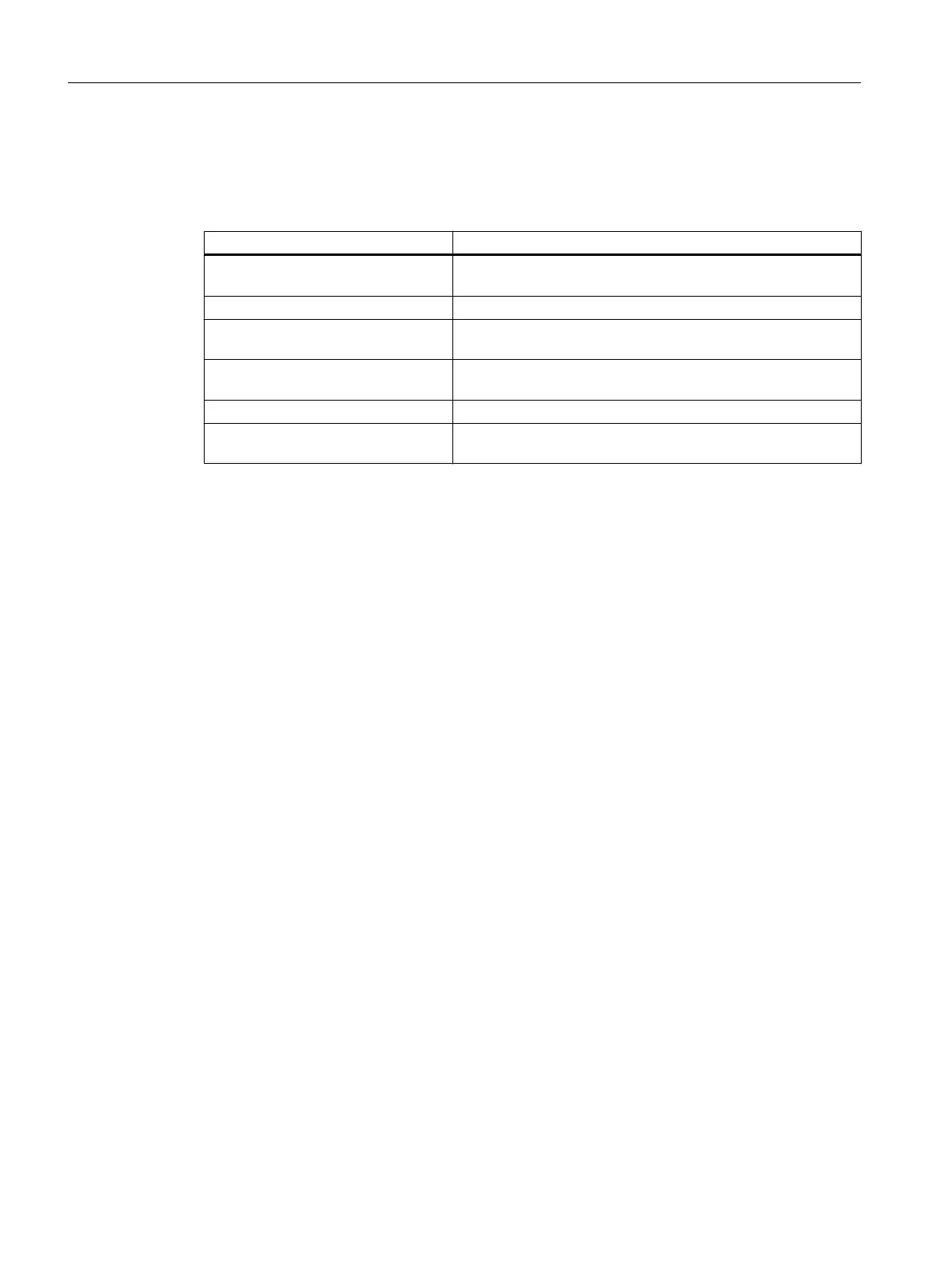
Table 3-3 Status and fault displays behind the front cover (C240 PN)
LED Meaning
Ethernet link (X7) (green) This LED indicates a physical connection of the Ethernet inter‐
face.
Ethernet activity (X7) (yellow) This LED indicates a data transfer via the Ethernet interface.
PROFINET link (X11 Px) (green) This LED indicates a physical connection of the PROFINET
interface at port x.
PROFINET activity (X11 Px) (yellow) This LED indicates a data transfer via the PROFINET interface
at port x.
PROFINET fault (X11) (red) This LED indicates a fault at the PROFINET interface.
PROFINET sync (X11) (green) This LED indicates synchronization status of the PROFINET
interface.
See also
Diagnosis using the LEDs (Page 157)
Operator control (hardware)
3.2 Display elements
SIMOTION C
40 Operating Instructions, 11/2016, A5E33441428B