03.2004 Monitoring
Siemens AG 6SE7087-7CX87-2DA0
SIMOVERT MASTERDRIVES Unité de Freinage / Braking Unit 5-1
5 Monitoring
In the case of faults, the braking
unit will be locked, the fault relay
(X38:4-5) is de-energized. The
fault is displayed via LEDs at the
front cover of the braking unit.
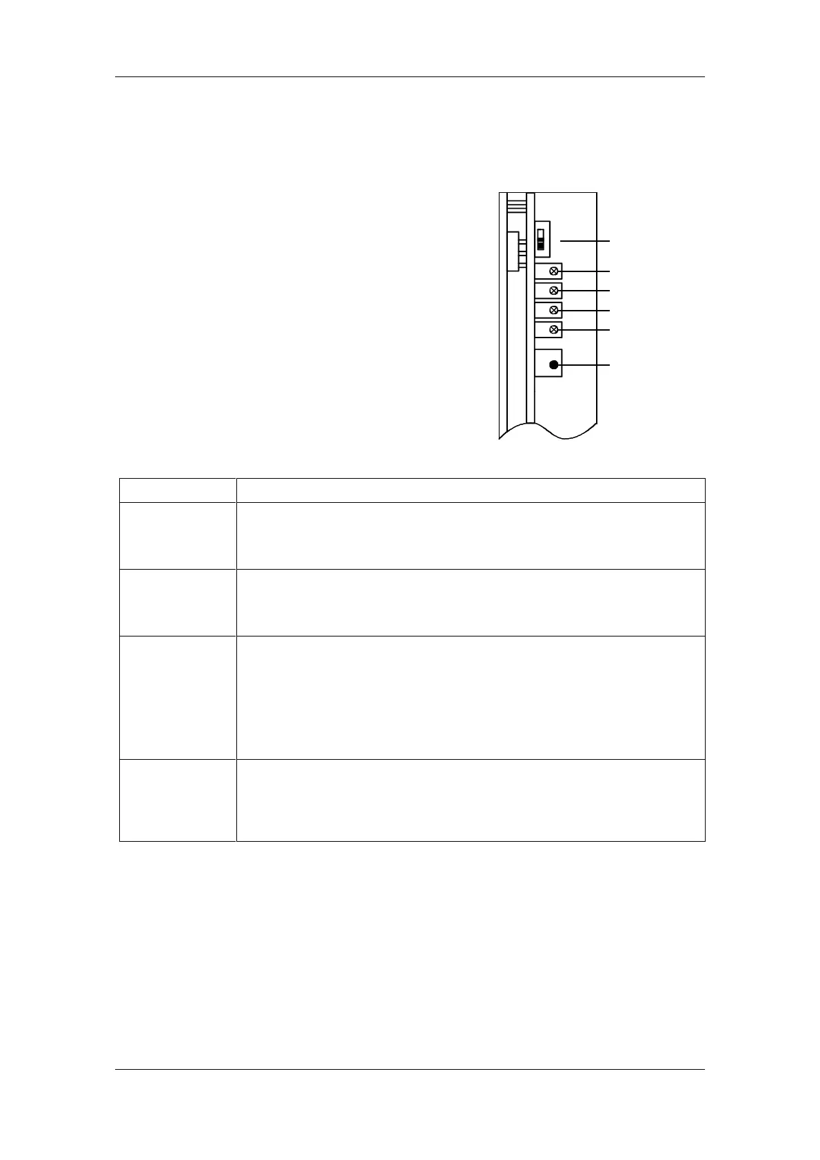
Displays (LED) Description of operating state
i OVERAMP LED is on during an output short circuit. This fault is not automatically reset. It can
be reset via the Reset key or by applying and releasing the Inhibit command.
Before resetting the braking unit make sure that the short circuit no longer
exists!
i OVERLOAD LED is on when the overload monitoring circuit becomes active (it monitors the duty
cycle); if the specified duty cycle is exceeded, the braking unit turns off. The fault is
automatically reset after some 70 sec.
Cannot be reset with the Reset key or by applying the Inhibit signal.
i OVERTEMP LED is on when the temperature monitoring circuit is active (ambient temperature
too high or no sufficient cooling air flow).
When the resistor overtemperature LED is lit, this means for
• braking power ≤ 20 kW excess temperature, internal brake resistor
• braking power ≥ 50 kW excess temperature, power semiconductor
The fault can be acknowledged when the critical temperature is fallen-below using
the reset button or by connecting the inhibit signal.
i READY LED is on after DC bus voltage is applied to the input terminals.
During operation the LED becomes darker with increasing duty cycle
(Note: a bright LED shows that additional braking power is available).
The LED extinguishes if the braking unit is disabled via the "inhibit" input of the X38
control terminal strip.
♦ Reset key is accessible through the front cover to reset
an overcurrent or excess temperature fault
♦ Voltage limit switch is accessible after removing the front cover
(see chapter 6 "Start-up").
-AMP
-Load.
-Temp.
Ready
Reset
1
2
V
E
R
O
Voltage Limit
Switch
Fig. 5-1 Position of the displays
Operating elements
 Loading...