Easy Start Guide
Page 10
This guide has been produced by The Inverter Drive Supermarket Ltd.
All content, including but not limited to graphics, text and procedures copyright The Inverter©
Drive Supermarket and must not be reproduced or altered without prior written permission.
9. How to connect and configure a Run Forward or
Run Reverse switch
9.1 Parameters to change for remote Run/Stop
The procedure described in Section 7 enable
Run/Stop operation via the red and green
buttons on the Inverter.
If this is unsuitable for the application, a remote
switch can be used instead.
This section explains how to enable 2-wire
control with Run Forward / Stop / Run Reverse
commands via a single selector switch.
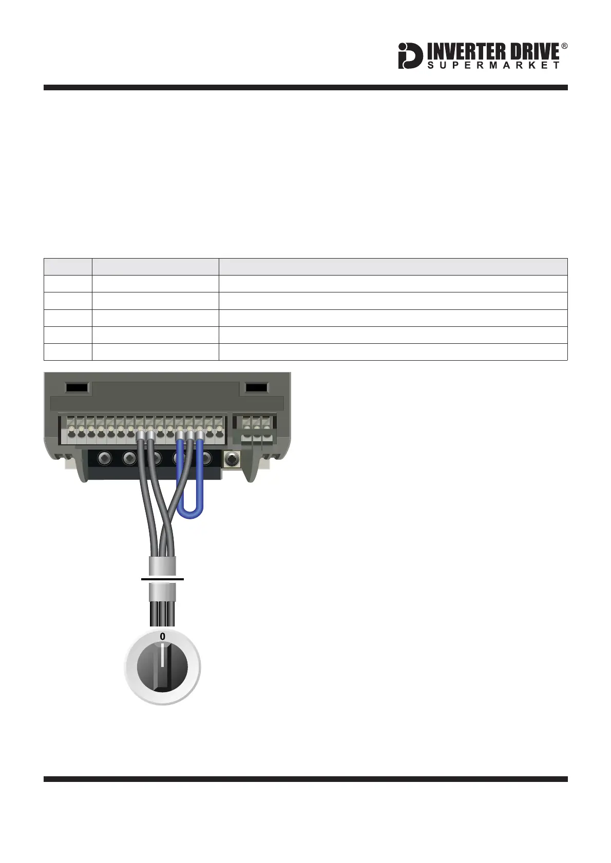
9.2 Connecting the Switch
A wiring diagram is shown in the illustration
opposite. The 24V terminal is a common
connection for terminals DI1 and DI2. Note that
DIC and 0V must be linked (blue wire).
A suitable 3 position NO (Normally Open)
switch should be installed between terminals
DI1, DI2 and 24V. The centre position should
remain open circuit.
When a connection is made between terminals
DI2 and 24V, the motor will run forward. When
terminals DI1 and 24V are connected, the
motor will run in reverse.
If terminals DI1 and DI2 are connected to 24V
at the same time the motor will stop.
FR
213
Switch, 3 Position
Normally Open
“Run Forward / Stop / Run Reverse”
[Order Codes 21720 and 21690 x 2]
Siemens V20 Series Inverter
W DC- DC+
DI 1
DI 2
DI 3
DI 4
DI C
24V
0V
D0 1+
DO 1-
DO2
NC
DO2
NO
DO2
C
UV
10V
AI 1
AI 2
AO 1
0V
P+
N–
12
3
Set to to allow access to extended parameters.2
Selection of command source
Set value to for terminals as command source (select index first if prompted).2 in000
Function of digital input 1
Set value to for ON reverse (select index first if prompted).2 in000
Function of digital input 2
Set value to for ON (select index first if prompted).1 in000
Selection of 2/3-wire method
Set value to to enable 2-wire (fwd / rev) control (select index first if prompted).1 in000

 Loading...


