Easy Start Guide
1. Power and Motor Connections (Single Phase)
Page 2
This guide has been produced by The Inverter Drive Supermarket Ltd.
All content, including but not limited to graphics, text and procedures copyright The Inverter©
Drive Supermarket and must not be reproduced or altered without prior written permission.
Notes:
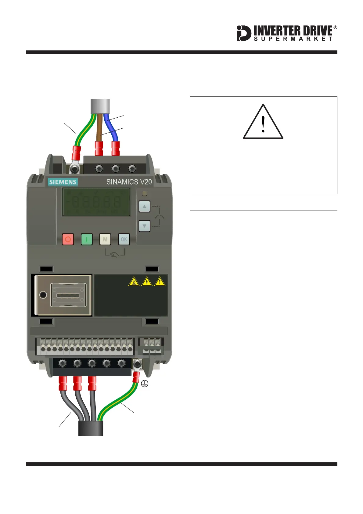
The illustration on the left is based on the
smaller 230V Single Phase frame size model
(to 0.75kW). The terminal layout for larger
frame sizes is similar.
The order of the three motor phases
determines the direction the motor turns.
Use screened cable between the Inverter and
Motor. To minimise electromagnetic
interference, ensure the cable screen is
grounded.
L1 L2/N L3
W DC- DC+
DI 1
DI 2
DI 3
DI 4
DI C
24V
0V
D0 1+
DO 1-
DO2
NC
DO2
NO
DO2
C
UV
10V
AI 1
AI 2
AO 1
0V
P+
N–
DANGER
RISK OF ELECTRIC
SHOCK! HAZARDOUS VOLTAGE PRESENT FOR
UP TO 5 MINUTES AFTER DISCONNECTION
FROM POWER SUPPLY! SEE INSTRUCTIONS!
PE
Earth
Earth
Neutral
Phases
Before commencing, confirm that the
Inverter and all cables are completely
isolated from the power supply, have
been isolated for at least 5 minutes and
that the motor is not turning.
SUPPLY
MOTOR
Live
Siemens V20 Series Inverter

 Loading...


