Installing the Control System
2-10
SINUMERIK 802S base line
Start-Up
2.3.2 Connecting the spindle measuring system (X6)
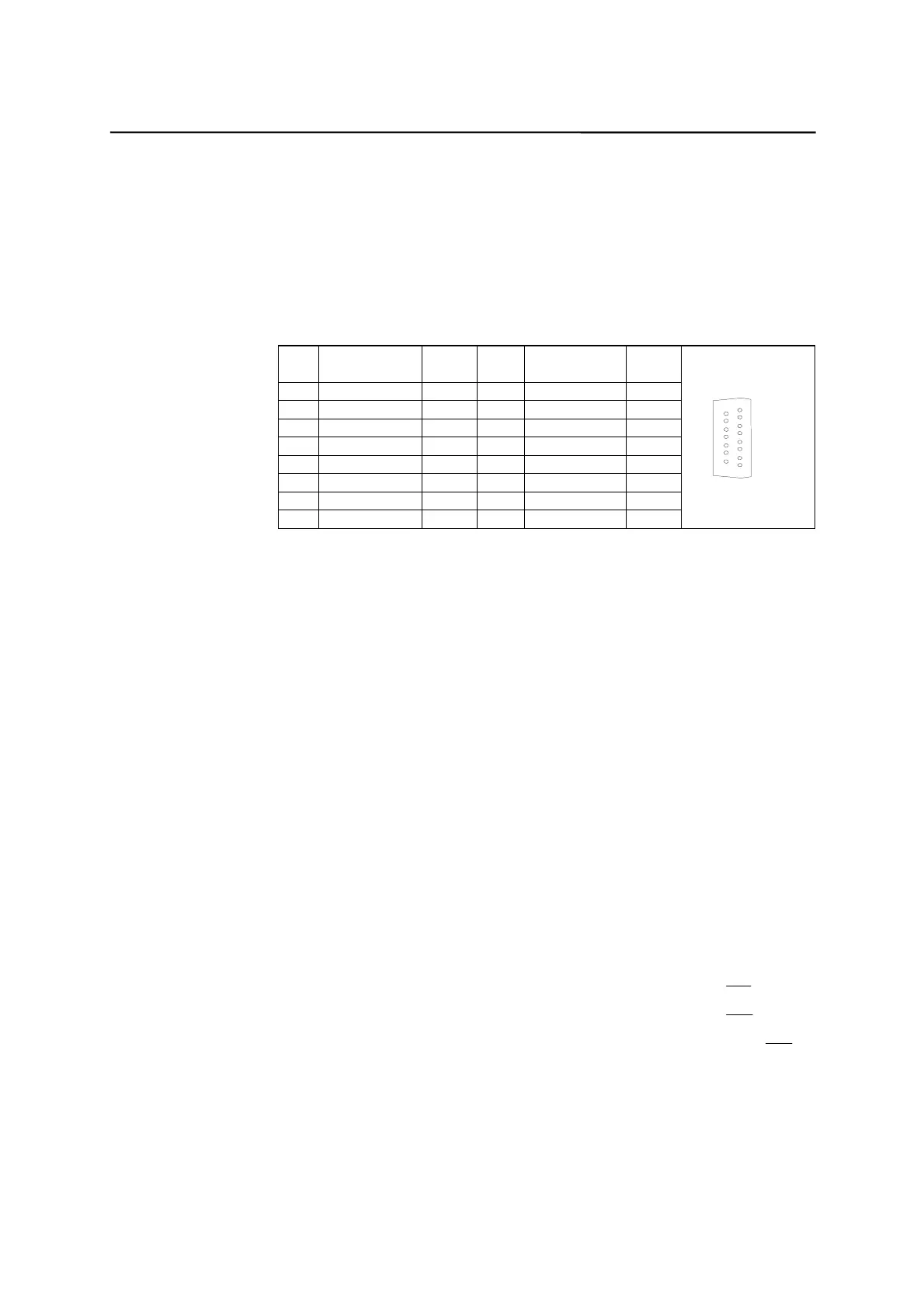
Pin assignment of the connector on the CNC side
Measuring system interface (incremental encoder)
Connector designation: X6
ENCODER
Connector type: 15-pin sub-D plug connector
Table 2–5 Pin assignment of the female connector X6
Pin Signal Type Pin Signal Type
1n.c. 9 M VO
2n.c. 10Z I
3n.c. 11Z_N I
4 P5_MS VO 12 B_N I
5n.c. 13B I
6 P5_MS VO 14 A_N I
7M VO15A I
8n.c.
1
8
9
15
Signal names Description
A; A_N Track A
B; B_N Track B
Z; Z_N Zero Reference Mark
P5_MS +5,2V Supply Voltage
M Ground
Signal Specification:
RS422
Signal type
VO Voltage output (supply)
I 5V input (5V signal)
Connectable encoder types
Incremental 5 V encoders can be connected directly.
Characteristics
The encoders must meet the following requirements:
Transmission method: Differential transmission with 5 V square-wave signals
Output signals: Track A as true and negated signal (U
a1
,
U
a
1
)
Track B as true and negated signal (U
a2
,
U
a
2
)
Zero signal N as true and negated signal (U
a0
,
U
a
0
)
Max. output frequency: 1.5 MHz
Phase offset between
tracks A and B: 90º ± 30º
Current consumption: max. 300 mA

 Loading...


