Start-Up
4-20
SINUMERIK 802S base line
Start-Up
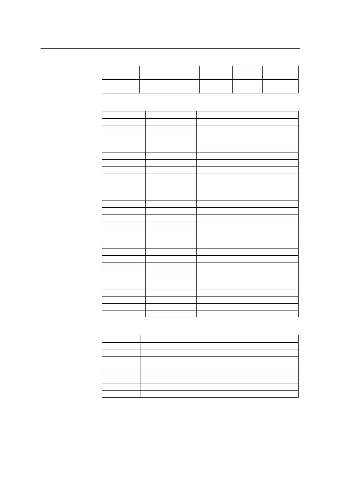
Table 4–8 Generating the addresses for the V range (see user interface)
Type Code
(DB No.)
Range No.
(Channel/ Axis No.)
Subrange Offset Addressing
00
(00-79)
00
(00-99)
0
(0-9)
000
(000-999)
symbolic
(8-digit)
Table 4–9 802S base line ranges of operands
Accessed by: Memory Type SINUMERIK 802S base line
Bit (Byte.bit) V 14000000.0-79999999.7
I 0.0 - 7.7
Q 0.0 - 7.7
M 0.0 - 127.7
SM 0.0 – 0.6
T 0 – 15
C0 - 31
L 0.0 - 59.7
Byte VB 14000000-79999999
IB 0 - 7
QB 0 - 7
MB 0 - 127
SMB 0
LB 0 - 59
AC 0 - 3
Word VW 14000000-79999998
IW 0 – 6
QW 0 – 6
MW 0 - 126
T0 - 15
C 0 – 31
LW 0 - 58
AC 0 - 3
Double Word VD 14000000-79999994
ID 0 – 4
QD 0 – 4
MD 0 – 124
LD 0 - 56
AC 0 – 3
Table 4–10 Special Flag SM Bit Definition
SM Bits Description
SM 0.0 Flags with defined ONE signal
SM 0.1 Initial position: first PLC cycle ‘1’, following cycles ‘0’
SM 0.2 Buffered data lost - applicable only to the first PLC cycle (‘0’
data o.k., ‘1’ - data lost)
SM 0.3 POWER ON: first PLC cycle ‘1’, following cycles ‘0’
SM 0.4 60 s cycle (alternating ‘0’ for 30 s, then ‘1’ for 30 s)
SM 0.5 1 s cycle (alternating ‘0’ for 0.5 s, then ‘1’ for 0.5 s)
SM 0.6 PLC cycle (alternating, one “0” cycle, then one “1” cycle)

 Loading...


