Commissioning Manual
01/2017
123
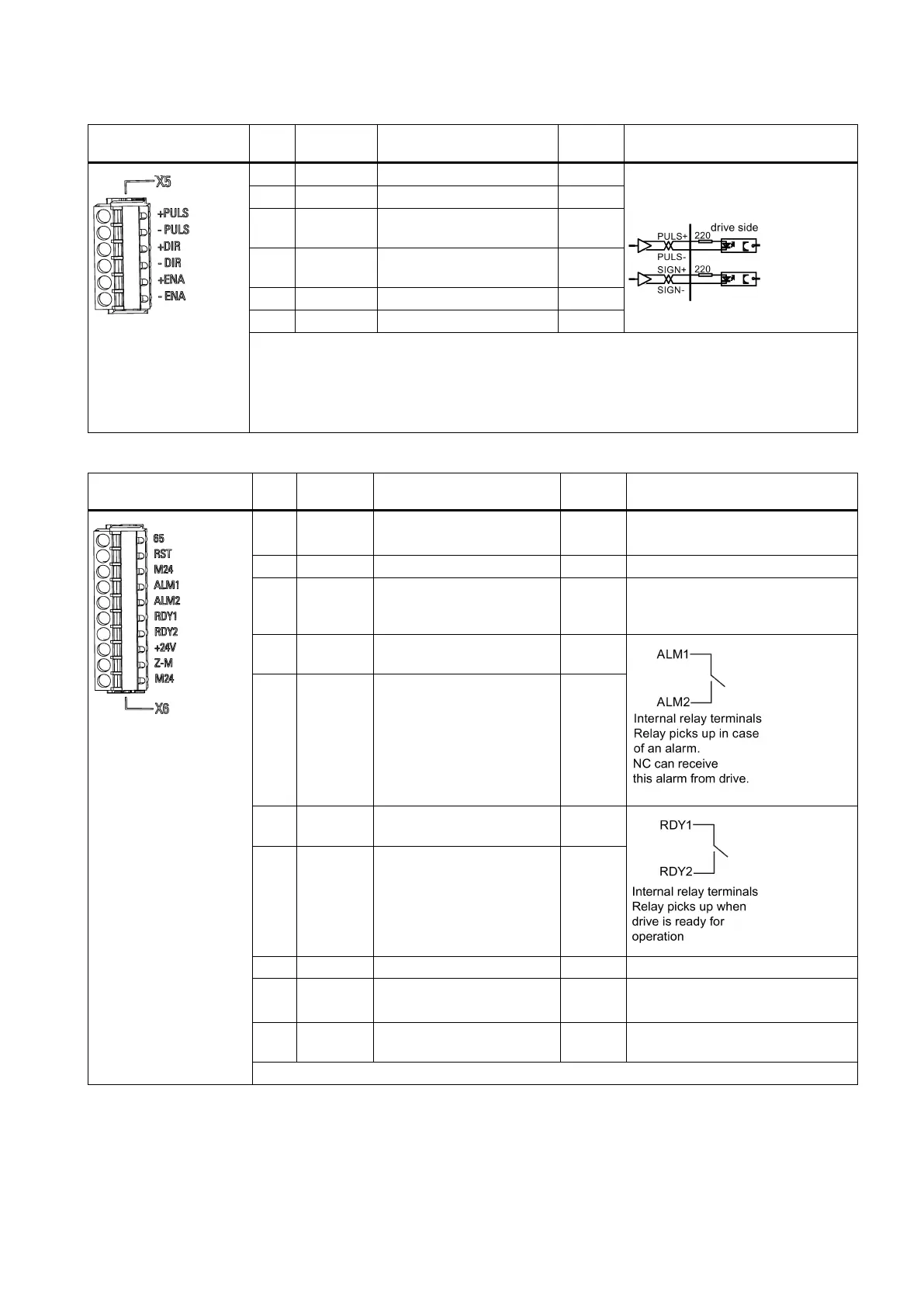
5V differential signal
Too high input voltage
may cause a damage to
the device.
Use the differential drive mode here
to transmit the pulse data correctly.
2 -PULS Pulse input setpoint - I
3 +DIR Direction of motor setpoint
I
4 -DIR Direction of motor setpoint
I
Max. conductor cross section: 0.5 mm
2
If the drive is connected with a SIMATIC PLC, please make sure that the time delay between
PULS and DIR signals should be more than 16 μs.
Please ensure that all the terminals of interface X5 should be firmly wired, otherwise, it is forbid-
den to start the machine.
Digital I/O interface - X6
1 65 Servo enable I +24 V = drive enable
1)
3 M24 Servo enable and alarm
cancel reference ground, 0
I
4 ALM1 Alarm relay contact 1 termi-
-
5 ALM2 Alarm relay contact 2 termi-
nal
-
6 RDY1 Servo ready contact 1 ter-
-
7 RDY2 Servo ready contact 2 ter-
minal
-
9 Z-M Zero mark output O Pulse width: 2~3 ms
10 M24 Zero mark reference ground
I
Maximum conductor cross section: 1.5 mm
2
1)
To cancel an active alarm, apply a high level (+24 V) at this terminal.

 Loading...


