Commissioning Manual
172 01/2017
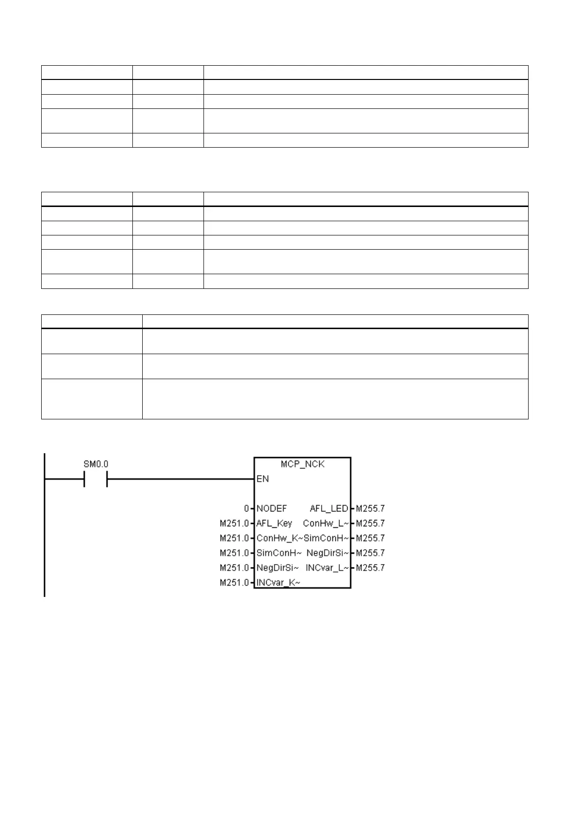
Define the Contour Handwheel at the MCP key
Define the simulation contour handwheel at the MCP key
NegDir-
BOOL Define the negative direction for simulation contour handwheel at the MCP key
Define the INCvar at the MCP key
1)
When the Auxiliary Function Lock function is active, all the outputs caused by auxiliary functions (like T, M, or S code)
are disabled, only with the axis moving as usual.
Define the Auxiliary Function Lock at the MCP LED
Define the Contour Handwheel at the MCP LED
Define the simulation contour handwheel at the MCP LED
NegDir-
BOOL Define the negative direction for simulation contour handwheel at the MCP LED
Define the INCvar at the MCP LED
Relevant PLC machine data
14512 [20].0 Grey coded switch (0: spindle override controlled by the grey mode; 1: spindle override con-
trolled by trigger user keys)
14512 [20].2 Activate the first additional axis (0: disable the additional axis control; 1: enable the additional
axis control)
14510 [12] Layout of the traverse keys
• For a turning variant, 0: horizontal version; 1: inclined version
• For a milling variant, 0: vertical milling; 1: knee-type
Example for calling subroutine 37

 Loading...


