Commissioning Manual
01/2017
93
The 24 V power supply must be protective extra-low voltage in accordance with EN60204-1, Section 6.4, PELV (with M
ground).
Be sure not to connect the pin 2 of X301/302 to ground; otherwise, the CNC controller of the power supply could be
damaged!
Note
The 24 V output of X301/302 pin 2 comes from pins 47 to 50.
Note
Addressing ranges
X301: IB3, IB4, IB5, QB2, QB3
X302: IB6, IB7, IB8, QB4, QB5
Note
The connecting cable between the power source, load current supply connection, and associated reference potential M must
not
exceed the maximum permissible length of 10 m.
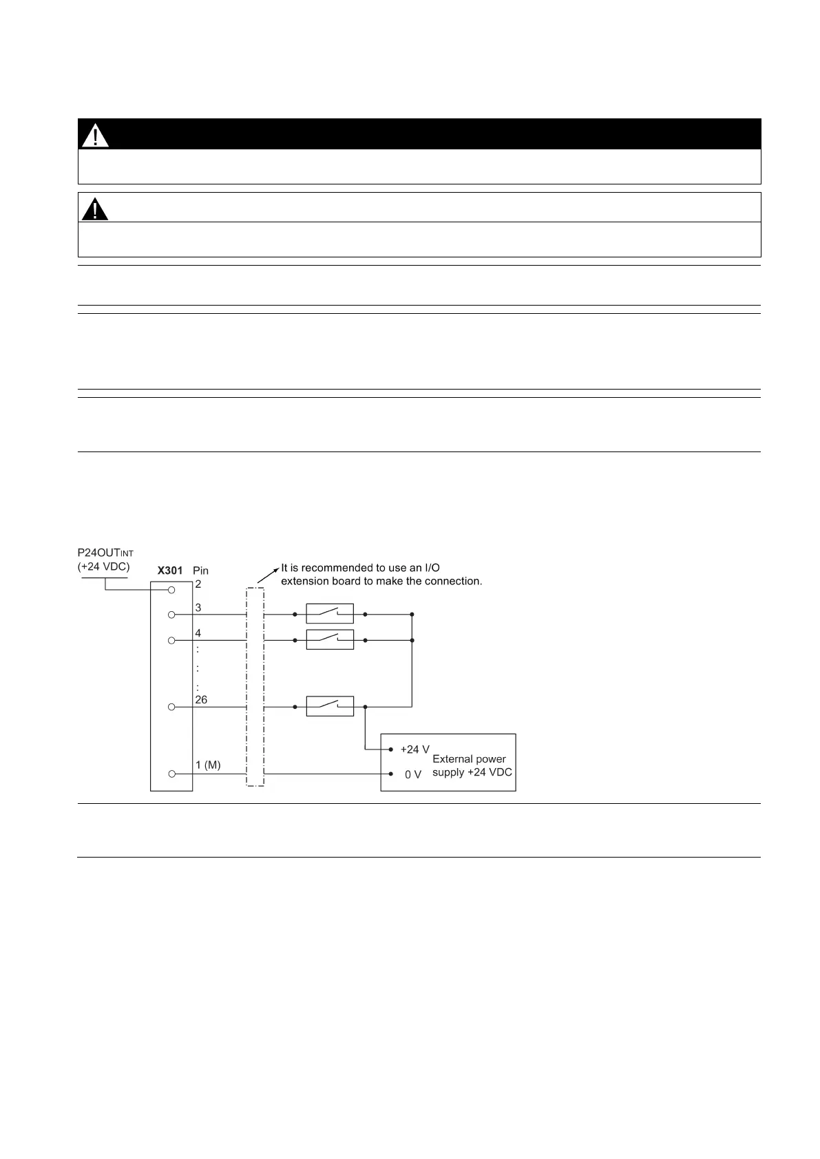
The diagram below shows you how to connect the connector pins of the digital inputs at interface X301 (example). You can
connect connector X302 in the same way.
Note
When using an external power s
upply, you must connect the 24 V (permissible range: 20.4 V to 28.8
V) power supply for the
digital outputs to all the four power input pins
(X301, X302:
).