1 Introduction 07.90
1.1 General
When measuring on the CNC machine, a distinction is made between two types of application,
i.e. tool measurement and workpiece measurement:
Tool measurement
For tool measurement, the changed tool (seated in the turret or in the tool spindle) is moved
onto the probe. The probe is either stationary or is swivelled or slid into the machine work area
by a mechanical device. The automatically determined tool geometry is subsequently entered
into a tool compensation memory provided for this purpose.
Workpiece measurement
For workpiece measurement, a probe is moved on the clamped workpiece in the same way as
a tool. The probe is fitted in the turret or in the tool slide, depending on the design of the
machine. The high flexibility of the measuring cycles enables nearly all measuring tasks
capable of being performed on a turning or milling machine to be accomplished sucessfully.
On the following pages, different measurement variants are illustrated selected according to
the criteria of flexibility, accuracy and duration of measurement.
1.2 Measurement variants
1.2.1 Measurement variants for turning machines
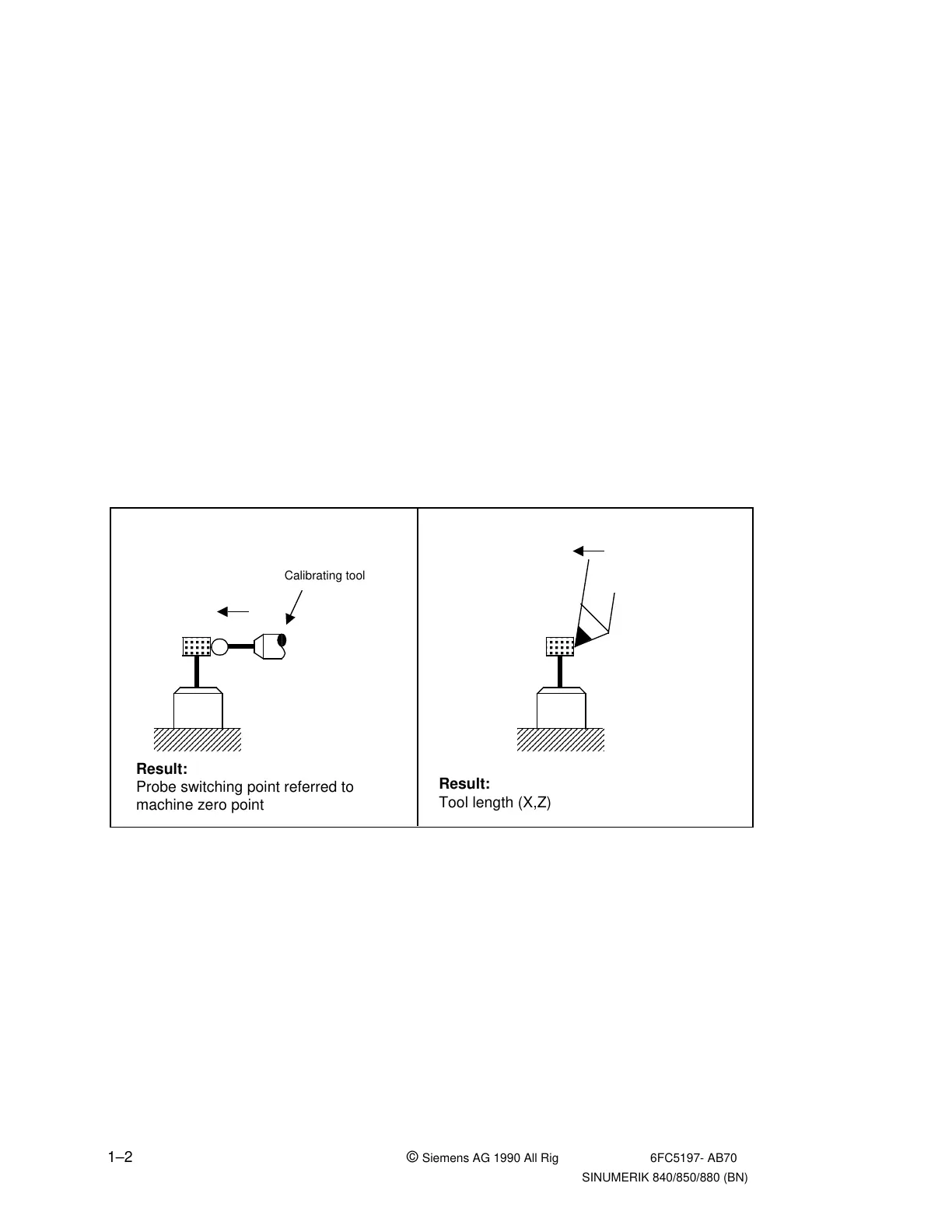
Fig. 1.1 Tool measurement
Calibrate tool probe Measure tool
a
a
a
a
a
a
a
a
a
a
a
a
a
a
a
a
a
a
a
a
a
a
a
a
a
a
a
a
a
a
a
a
a
a
a
a
a
a
a
a
a
a
a
a
a
a
a
a
a
a
a
a
a
a
a
a
a
a
a
a
a
a
a
a
a
a
a
a
Calibrating tool
a
a
a
a
a
a
a
a
a
a
a
a
a
a
a
a
a
a
a
a
a
a
a
a
a
a
a
a
a
a
a
a
a
a
a
a
a
a
a
a
a
a
a
a
a
a
a
a
a
a
a
a
a
a
a
a
a
a
a
a
a
a
a
a
a
a
a
a
a
a
a
a
Result:
Probe switching point referred to
machine zero point
Result:
Tool length (X,Z)
1–2 © Siemens AG 1990 All Rights Reserved 6FC5197- AB70
SINUMERIK 840/850/880 (BN)