08.96 5 Measuring Cycles for Milling Machines and Machining Centres
5.1.4 L976 Calibrating workpiece probe on any surface (applicate)
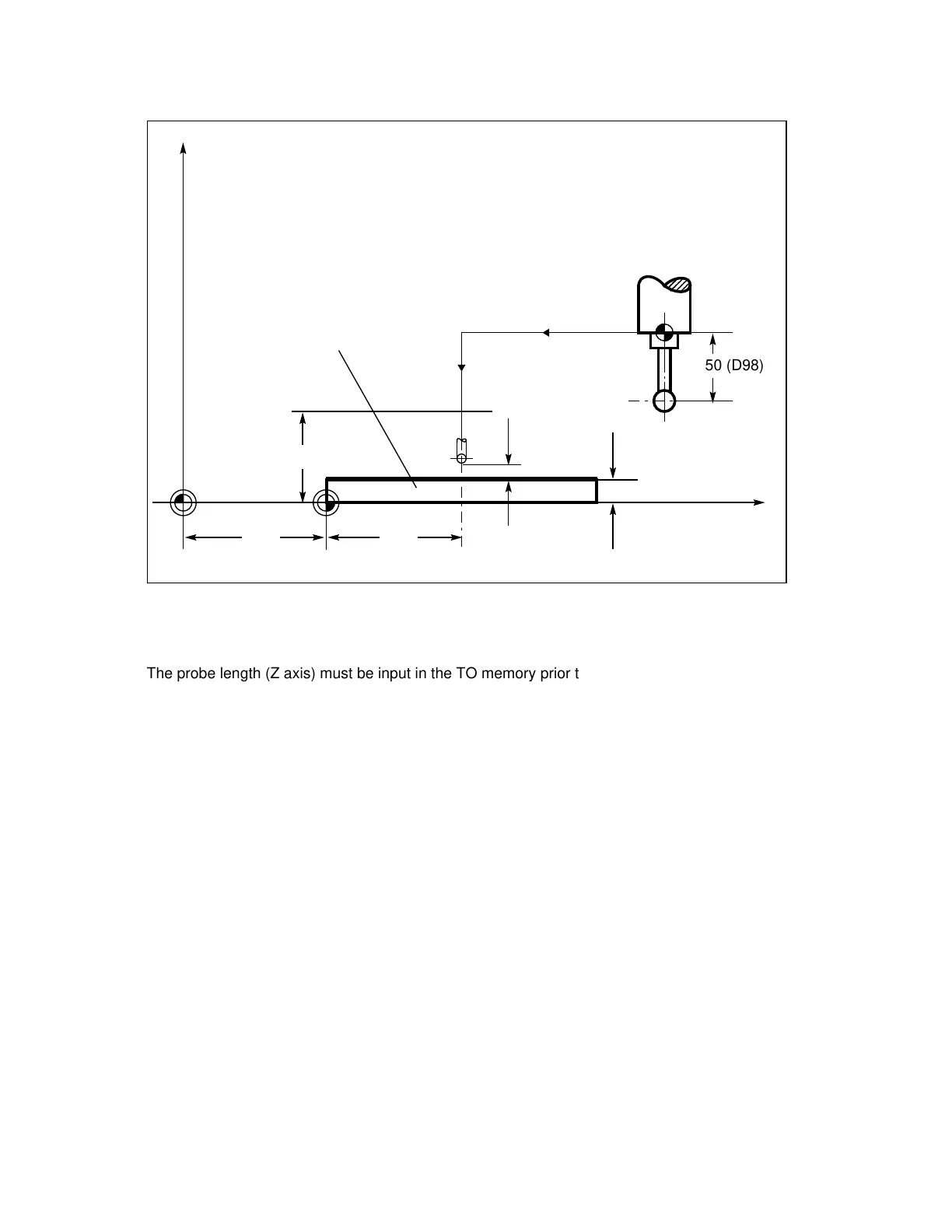
Example: Calibrating workpiece probe 1 in the Z axis at the workpiece
Fig. 5.6 Any calibration surface
”a”
W
N15
N10
Z
M
100
20 (R32)
100
55
Workpiece
X
F
a
a
a
a
a
a
a
a
a
a
a
a
a
a
a
a
a
a
a
a
a
a
a
a
a
a
a
a
a
a
a
a
a
a
a
a
a
a
a
a
a
a
a
a
a
a
a
a
a
a
a
a
a
a
a
a
a
a
a
a
a
a
a
a
a
a
a
a
a
a
a
a
50 (D98)
The probe length (Z axis) must be input in the TO memory prior to cycle call, e.g. D98 (in this
case value 50).
%MPF 9766
N5 T200 T No. probe
N10 G54 G17 G00 X100 Y80 Position probe above calibration point
N15 D98 Z55 Select length compensation
N20 R22=1 R23=23 R25=0 R27=1 Parameters for calibrating cycle
R28=1 R32=20 R33=0 R36=1
R30=3 R31=1
N25 L976 Cycle call for calibrating in the
Z axis
N30 M30
The new trigger value is entered in the relevant MDC.
©
Siemens AG 1990 All Rights Reserved 6FC5197- AB70 5–13
SINUMERIK 840/850/880 (BN)