1 Introduction 08.96
1.5.2 In-process measurement
Measurement path a/measuring speed
Normally, the path increment is 1 mm. It can, however, be increased or reduced when calling
the measuring cycles with parameter R 28. The approach speed increases automatically from
155 mm/min to 300 mm/min when defining the value for a>1. This value has been chosen to
make sure that the deceleration distance is less than the permissible probe deflection.
For measuring cycles the measuring speed can be preset via parameter R 25 as desired.
However, safe deceleration within the deflection path of the probe should be ensured.
Hence, the maximum approach speed (measuring speed) depends only on
• the permissible deflection path the probe used
• the delay until ”delete distance to go” is executed and
• the deceleration behaviour of the axis.
Example:
Deceleration path calculation
s
1
s
2
v
2
2b
s
b
= v
.
t + + s
S
b
v
t
b
s
Deceleration path
Approach speed
Delay
Deceleration delay
Following error
in m
in m/s
in s
in m/s
2
in m
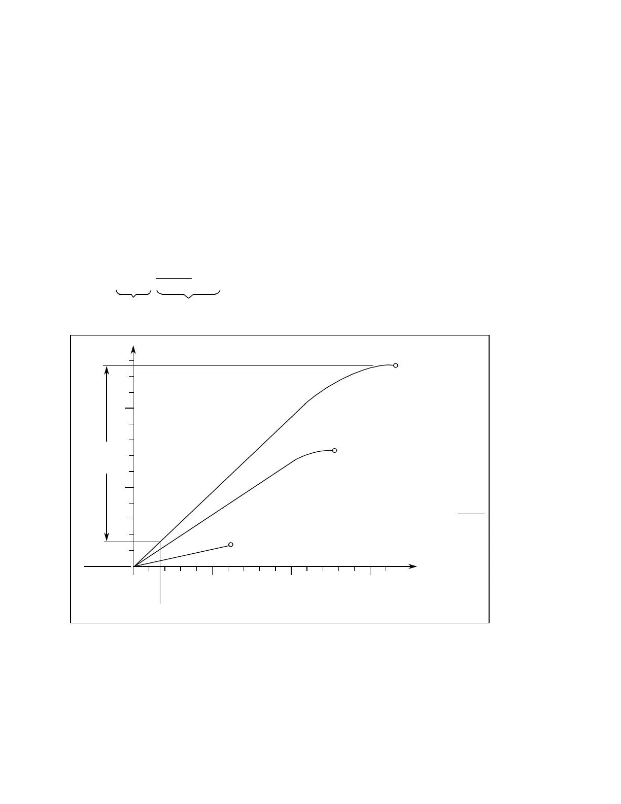
Fig. 1.17 Path/time diagram
1 m/min
Zero speed
4 m/min
Zero speed
6 m/min Approach speed V
Zero speed of axis
s
1
(1.66 mm)
(16 ms) Delay until distance to go is deleted
10
150100500
5
s [mm]
t [ms]
s
2
(11 mm)
Acceleration a = 1 m/s
2
Kv factor = 1
m/min
mm
The deflection of the probe until the axis reaches zero speed is approx. 12.6 mm in the case
of an approach speed of 6 m/min and a delay of 1 m/s
2
.
1–16 ©
Siemens AG 1990 All Rights Reserved 6FC5197- AB70
SINUMERIK 840/850/880 (BN)