1 Introduction 10.91
1.9.2 Logging via CP315 with the SINUMERIK 840/880
Z
X
a
a
a
a
a
a
a
a
a
a
a
a
a
a
a
a
a
a
a
a
a
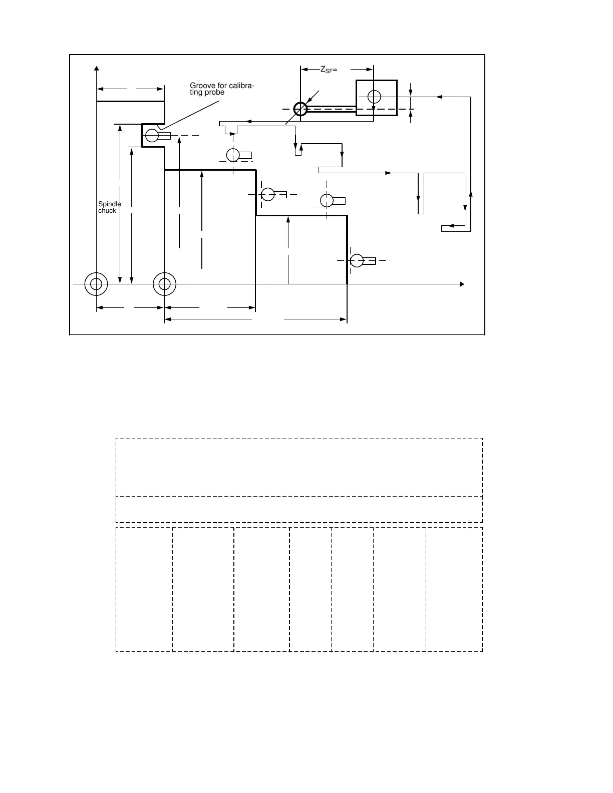
Spindle
chuck
Groove for calibra-
ting probe
Z
SF
=50
d=10
F
X
SF
=25
N135
50
140
120
260
200±0,3
Workpiece
Measuring
point 3
Measuring
point 4
Measuring
point 1
Measuring
point 2
70 50±0,2
100±0,3
M
150±0,5
N30
N55
N60
N65
N80
N85
N105
N100
N110
N125
N130
W
– The following test log is to be output:
Column 12345678901234567890123456789012345678901234567890123456789012345678901234567890
10 20 30 40 50 60 70 80
Line
0001.0
4+1 decimal
place +
fixed point
from the PLC
3111.180
8 places
without sign
with decimal
point 4 places
before,
3 places after
decimal point
(R206)
3112.303
8 places
(R209)
1.123
5 places
(R200)
–0.001
5 places
(R203)
1.123*
5 places
(R212)
09:46:02
8 places
Part number . . . . . . :<23456789> (R40) Date: dd.mm.yy// / Page: No.
Order number . . . . . :<23456789> (R41)
Program number . . . :<23456789> (R43) Serial number . . . . :<23456789> (R44)
Measuring Setpoint Actual value Tolerance limit Setpoint Time of day
point + – difference
1
2
3
4
5
6
7
8
9
10
11
12
13
14
15
16
17
18
19
20
21
22
R parameters in brackets do not appear on the log. They only serve as an indication in which
columns or lines the parameter contents are entered.
1–40 ©
Siemens AG 1990 All Rights Reserved 6FC5197- AB70
SINUMERIK 840/850/880 (BN)