10.91 4 Measuring Cycles for Turning Machines
4.1 L972/L982 Tool measurement
Description of tool types 26, 28, 31 ... 38
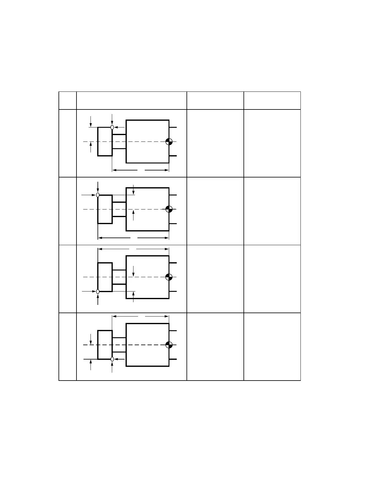
Tool types 31 ... 34, R23=00xx
With tool types 31 ... 34, the lengths L1 and/or L2 are measured at the selected corner point
of the milling cutter and compensated in the tool offset memory.
Axial tools
Axial tool form
Tool
type
Tool geometry
dimensions
Dimensions
compensated
31
32
33
34
L1, L2,
R=0
L1, L2
L1, L2L1, L2,
R=0
L1, L2,
R=0
L1, L2
L1, L2L1, L2,
R=0
–L1
Measuring point
L2
–L1
Measuring point
L2
+L1
Measuring point
+L1
Measuring point
L2
L2
F
F
F
F
© Siemens AG 1990 All Rights Reserved 6FC5197- AB70 4–3
SINUMERIK 840/850/880 (BN)