10.91 4 Measuring Cycles for Turning Machines
4.1 L972/L982 Tool measurement
Tool types 28, 37 and 38, R23=x1x2
With tool type 28, L1 and R
are determined.
With tool types 37 and 38, L1, L2 and R
are determined.
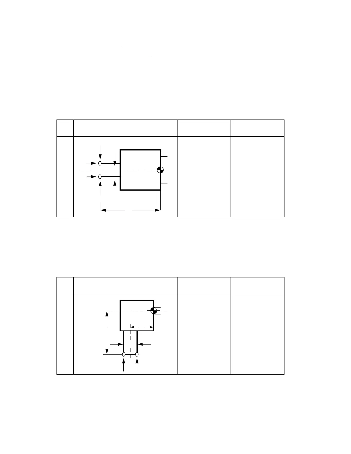
The first measuring point is measured in the abscissa and ordinate. The tool is then turned
through 180 degrees and the same cutting edge is measured again in the two axial directions.
The average values of the two measurements provide the L1 and L2 dimensions. The cutter
radius is determined from half the dimensional difference between measuring point 1 and
measuring point 2 in the ordinate.
Axial tool
37
L1=0
L2, R
L1, L2, R
L2
Measuring point 2
Measuring point 1
L2
Axial tool form
Tool
type
Tool geometry
dimensions
Dimension
compensations
F
R
Calculation of tool geometry:
L1=(L1,1+L1,2)/2 L2=(L2,1+L2,2)/2 R=ABS((L1,1 – L1,22)/2)
Radial tool
28
38
L1, L2=0, R
L1, L2, R
L1, R
L1, L2, R
Measuring
point 1
L1
R
Measuring
point 2
Axial tool form
Tool
type
Tool geometry
dimensions
Dimension
compensations
F
L2
Calculation of tool geometry:
L1=(L1,1+L1,2)/2 L2=(L2,1+L2,2)/2 R=ABS((L2,1 – L2,2)/2)
©
Siemens AG 1990 All Rights Reserved 6FC5197- AB70 4–7
SINUMERIK 840/850/880 (BN)