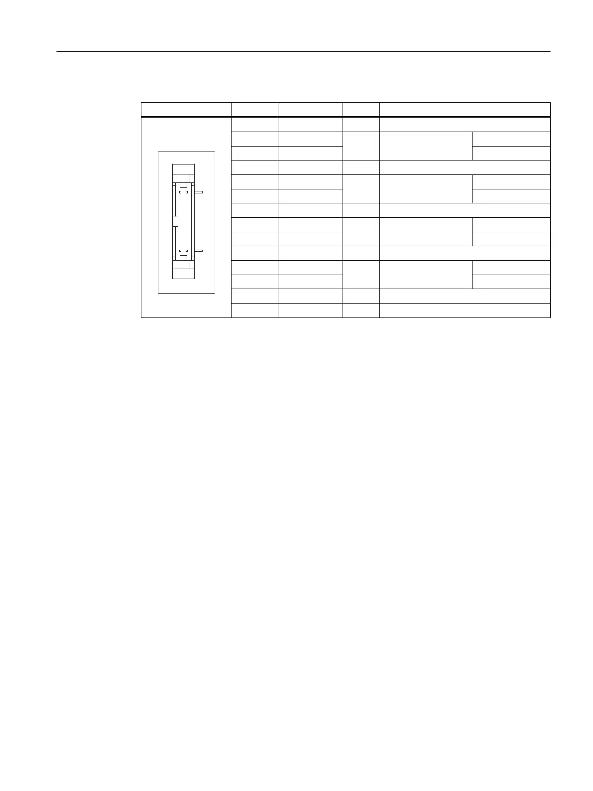
Table 4-6 Allocation of the LVDS display interface
Connector Pin Name Type Meaning
1/2 GND - System ground (reference potential)
3 RXIN10-
I
LVDS input signal Bit 0 (-)
4 RXIN10+ Bit 0 (+)
5/6 GND - System ground (reference potential)
7 RXIN1-
I
LVDS input signal Bit 1 (-)
8 RXIN1+ Bit 1 (+)
9/10 GND - System ground (reference potential)
11 RXIN2-
I
LVDS input signal Bit 2 (-)
12 RXIN2+ Bit 2 (+)
13/14 GND V Ground
15 RXCLKIN-
O
LVDS cycle clock sig‐
nal
(-)
16 RXCLKIN+ (+)
17 GND V Ground
18-20 P12VF VO +12 V fused
4.1.5 Direct key interface
X11 on the operator panel (OP) fronts can be used to fetch the state of the direct keys. The
connection of a 20-pin ribbon cable allows the direct keys to evaluate the following components:
● Direct key module (DTM)
● X70 in the machine control panels (MCP, MPP) and the handwheel connection module
(HAM)
● X205 on the Thin Client Unit (TCU)
The signals are then forwarded to the control over the various communications networks. Note
that DTM and HAM can be operated only with PROFIBUS DP.
Connection
4.1 Pin assignment of the interfaces
TCU 30.3
Manual, 09/2017, A5E40874197 29

 Loading...