03.06
4.4 Cable distributor (distributor box)
4-57
© Siemens AG, 2006. All rights reserved
SINUMERIK 840D Configuring Manual NCU (PHD) – 03.06 Edition
Insert the upper terminal bar in such a way that its “teeth” are facing the “teeth”
of the lower terminal bar and then secure the upper housing section.
This will reliably press the cable shields between the contact areas of the con-
tact springs and contact them. Securing to the front panel of the NCU routes the
shield potential via the contact springs of the cable distributor.
Status table for switches S1...S5 (Order No. 6FX 2006-1BA00)
The DIP FIX switches in the cable distributor must be set as follows:
Table 4-12 Setting the DIP-FIX switches in the cable distributor (S1...S5)
Switch
S1 S2 S3 S4 S5
Open x x x x x
Closed
Status table for switches S1...S6 (Order No. 6FX 2006-1BA01)
The DIP FIX switches in the cable distributor must be set as follows:
Table 4-13 Setting the DIP-FIX switches in the cable distributor (S1...S6)
Switch
S1 S2 S3 S4 S5 S6
Open x x x x
Closed x x
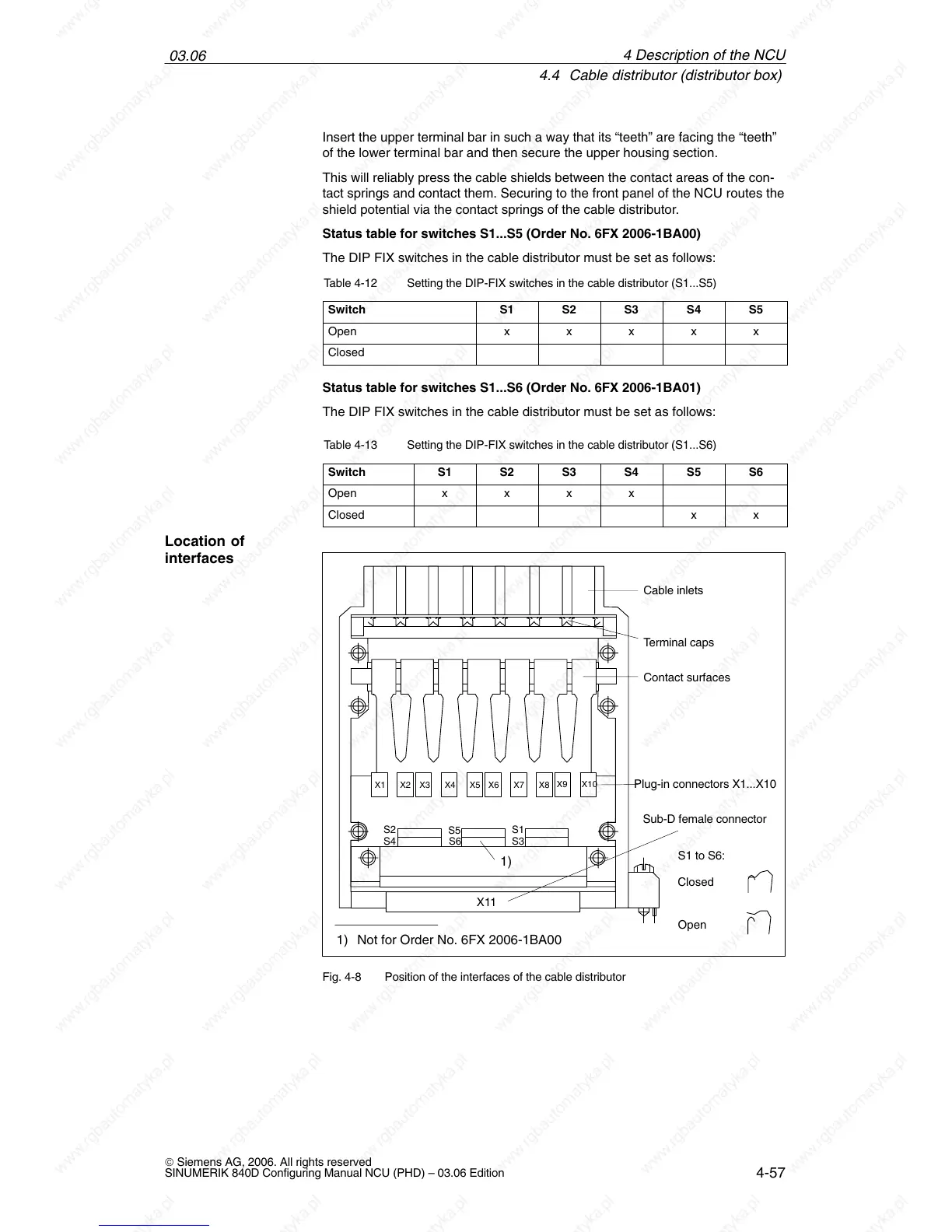
Open
Closed
X1 X2 X4 X5 X6 X7 X8
X9 X10
X3
X11
Cable inlets
Terminal caps
Contact surfaces
Plug-in connectors X1...X10
S3S4
S5
S1S2
Sub-D female connector
S6
1)
1) Not for Order No. 6FX 2006-1BA00
S1 to S6:
Fig. 4-8 Position of the interfaces of the cable distributor
Location of
interfaces
4 Descri
 Loading...


